
Tracking Soviet Television Satellites
By Mark Dahmke
Originally published in Circuit Cellar Ink, August, 1989, Issue #10.
In recent years, due to lower cost and greater availability of satellite receiver technology, it has become possible to watch television programs from many other countries in this hemisphere. I've always had an interest in Europe and the Soviet Union and wanted to monitor their television, but due to the curvature of the Earth and the use of focused spot beams, there are limits to what can be seen from central North America. In 1985 I learned that the Soviet Union operates a system of satellites in polar orbit which are used to broadcast television to northern Siberia. Because of their unusual orbits, they are visible to most of the northern hemisphere.

SIBERIAN LIGHTNING
In the mid-1960s, the Soviet Union needed a way to broadcast to the northern and eastern regions of Siberia. In the United States, we have been using geostationary "Clarke" orbits (named for Arthur C. Clarke, who first conceived of the communications satellite) for such a long time that it's hard to think in terms of any other kind of orbit for broadcast television. The main advantage of a satellite in geostationary orbit is that you can point a dish at the satellite and never have to move it again. The trouble is that geostationary satellites aren't very useful for receiving sites above 70 degrees north latitude, and in the mid-60s the Soviet Union didn't have the capability to launch a large payload into a geostationary orbit anyway. The Soviets had other requirements, and have always been good at using available technology to meet their needs.


The Molniya orbit (pronounced Moln-ya, meaning "lightning" in Russian) has several unique properties. First, it is a polar orbit, inclined 63 to 65 degrees With respect to the equator. Two periods are possible: one just under 12 hours and the other just under 24 hours. The Soviets chose the 12-hour orbit for their system. The eccentricity is 0.74 which means that it is highly elliptical. Figure 1 shows the properties of this orbit from a stationary point of view out in space. The orbit's apogee (high point) is at about 40,000 km and the perigee (low point) is 600 km. While remarkable in terms of conventional geostationary satellites, there are additional unusual features. Since the orbit has a period of 12 hours, the satellite will appear to be at its apogee over Hudson Bay, Canada during one orbit, then, because the Earth has revolved through 180 degrees underneath it, the next apogee will be over central Siberia. The effect of this combination of satellite motion and the Earth's rotation means that the satellite will repeat its ground track very accurately each day. Only a limited number of stable ground tracks exist in this configuration, and the Soviets chose an ascending node of approximately 113 degrees West. Figure 2 shows the apparent ground track of this Orbit.
From a location in the central United States, the satellite would appear to rise above the southern horizon rapidly traverse the sky from almost due south to the zenith, then move into the northern sky. As it reached its apogee, it would appear to move more slowly and almost come to a stop, and generally never drop below 60 degrees altitude in the northern sky. As it started to fall from its maximum altitude, it would move faster and begin to move back toward the zenith, eventually moving into the southern sky and dropping below the horizon. Figure 3 shows its apparent position in the northern Sky. A satellite would repeat this track once per day because its next climb to apogee would be over Siberia and wouldn't be visible to us in North America (actually, it would be visible but be very low on the northern horizon).
During the Canadian active loop, the satellite would appear to an observer in Siberia (or Moscow) to pop up from the northern horizon for a few hours, rise to about 30 or 40 degrees in elevation, then drop down and disappear until the next day. The "visibility window" for a given satellite maybe up to eight hours. To solve this problem, the Soviet Union uses four satellites spaced six hours apart in nearly identical orbits, allowing for almost continuous coverage. When each satellite rises above the horizon, it is switched on and used for six hours, until control is handed off to the next satellite. The question most people ask is: Why do they use the Canadian active loop, not the Siberian loop? There are two obvious answers: one is that both are used but since the Siberian loop is difficult to receive here, no one has really investigated this possibility. The second answer is that to track a satellite that is almost overhead means that the dish will collect a lot of snow and ice. A dish pointing at a satellite above Canada would be placed at an angle comparable to that used to watch geostationary satellites, but looking north instead of south. Wind load would be a problem, but perhaps less a problem than ice load (it is widely believed that the standard receiving dish diameter used in remote receiving locations in Siberia is about 10 meters).
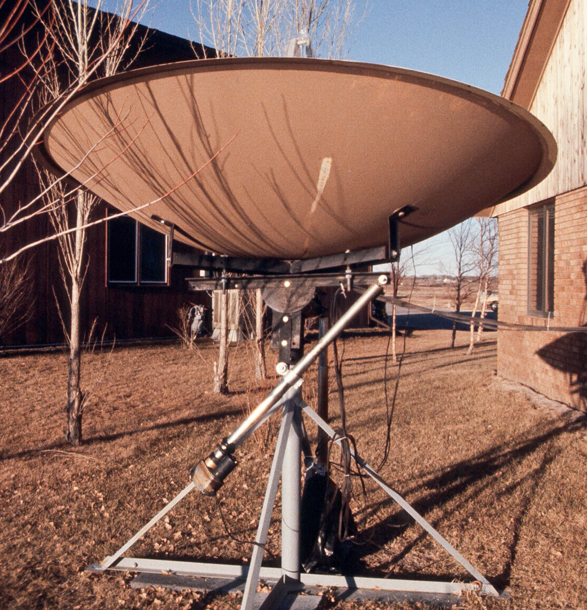
Photo 1: The author's eight-foot aluminum dish with modified polar mount. A standard polar mount can be modified to provide dual-axis control of the dish. The elevation adjustment is controlled by a second actuator and jack so the dish may be moved from a 45-degree angle up to and past 90 degrees. The normal east-west motion is controlled by an actuator just as on a normal dish mount. Note that the pedestal leg on the left side of the mount in this picture points 20 degrees east of North.
RECEIVING TECHNOLOGY
Since so much has been written lately about the differences between U.S. and European television technology, you might think that a design to receive Soviet television would require nothing but esoteric, hard-to-find parts. Surprisingly, it is possible to use off-the-shelf receivers, low-noise amplifiers, and feed horns with good results. The Molniya satellites broadcast in C-band just like domestic U.S. satellites, but use circular polarization rather than horizontal-vertical polarization. The single television signal available on the satellite has a downlink frequency of about 3874 MHz, or roughly half way between transponder frequencies 9 and 10 on domestic satellites. The FM audio subcarrier now used for TV audio is at 7.4 MHz. I’ve used a variety of low-cost receivers with excellent results, but for a first-rate signal and good control over bandwidth, a Chaparrel Sierra II or III receiver is ideal. Since circular polarization is used, you must insert a small teflon dielectric block into the throat of the dish feed horn which has the effect of rectifying or converting circular polarization into horizontal-vertical polarization. Without the teflon, you will experience a signal loss of 2 db, but with it, you will gain 2 db. The block can be ordered precut from Chaparrel Communications and other manufacturers. The second major difference is that the Soviet Union uses the SECAM television standard (a French acronym for Sequential Color With Memory). [Editor' s Note: For more details on TV standards see Ed Nisley’s article "ImageWise/PC" in CIRUIT CELLAR INK #6.] For the low-budget approach, a normal NTSC television will display a SECAM Signal, but only in black and white and with the wrong aspect ratio. If you're serious about international television, you can buy a multistandard receiver and VCR from companies like Sony and Hitachi. Prior to September 1988, the Soviets used a modified SECAM format in which the TV audio was added as a pulse next to the horizontal sync in each scan line. This "sound in sync" method was adopted before there were any standards for the transmission of audio on an FM subcarrier. The old method used pulse-width modulation and required a decoder circuit that would extract the audio using sample-hold techniques and then reconstruct a normal SECAM sync pulse for the monitor. Fortunately this technique has been phased out, greatly simplifying reception of Molniya broadcasts. The Signal strength from these satellites is quite high, comparable to the powerful transponders of Galaxy I. I've received marginal quality pictures using a mere six-foot dish and 135-degree LNA (Low-Noise Amplifier). My standard setup, shown in Photo 1, is an eight-foot (2.4-meter) solid aluminum dish with a 60-degree LNA (the noise temperature in Kelvin of an LNA rates its ability to amplify signals above the noise in the amplifier itself, the background radiation of the Earth, and from outer space). A few years ago, good-quality, low-temperature LNAs were extremely expensive, so the only option was to move to a larger diameter dish. Now, a 60-degree LNA costs less than a hundred dollars.
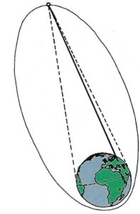
Figure 1: The ellipse represents the “true” 12-hour orbit, inclined 63.5 degrees out of the equatorial plane. The dashed lines show the signal coverage at apogee (maximum distance) which is approximately 24,860 miles above Hudson Bay, Canada. The solid line represents the signal uplink from Moscow. Each of four satellites is active for six hours each day, giving 24 hour coverage of Siberia.
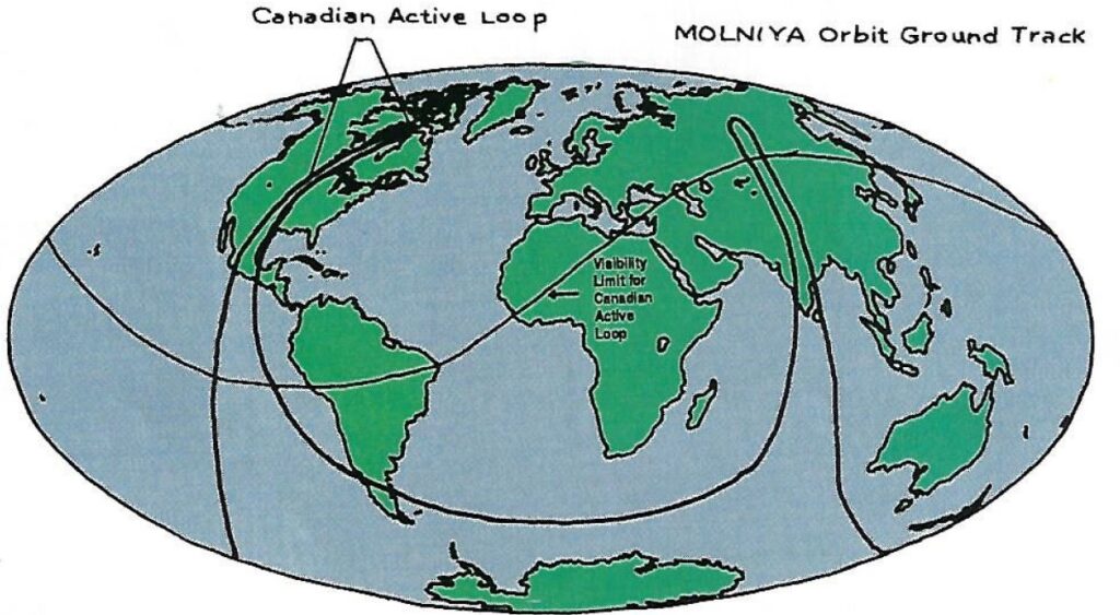
Figure 2: The dark line shows the apparent ground track of a typical Molniya Orbit. Note the two active loops, one over Hudson Bay. the other over Siberia. The Canadian active loop is used for television broadcasts to Siberia.
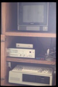
Photo 2: The receiver and computer control setup. The monitor on the top shelf is a Sony PVMJ271 13-inch multistandard unit. The receiver is an older model Drake; the power supply to its right supplies 32 volts DC at about 1 amp, which powers the actuators. The PC is an XT clone With 10-megabyte harddisk and custom-built controller card with A-to-D input and relay controls.
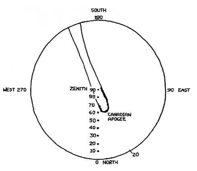
Figure 3: The Molniya orbit as seen from the US midwest. The dark part of the curve shows the active portion of the orbit - the period used to broadcast television.
TRACKING A MOVING SATELLITE
Now comes the fun part. It is possible to manually locate and track the Molniya satellites, and I've done so many times. But to really make this a fun project, and to set up an automated receiving station that a non-techie can use, we need some computer-controlled motors and analog-to-digital converters.
When planning to build a Molniya receiver, your location should be taken into account. In the central United States an eight-foot dish will work well, but if you live farther south, a ten- or twelve-foot dish would be advisable. A sixteen-foot dish maybe required at or near the visibility limit shown in Figure 2.
DISH POSITIONING
The dish you use must be steerable with two degrees of freedom. Several axis arrangements are possible: A simple azimuth-elevation mount will work, with rotation (azimuth) and elevation (altitude). The disadvantage of this approach is that the satellite often must be followed across the zenith point, which also happens to be on the rotational axis of the dish mount, resulting in a singularity. That is, you would be pointing straight up with the ability to rotate the dish around the azimuth axis, but it would always point to the same spot. A better arrangement is to have the rotational axis offset to some other part of the sky. Such an offset is easily accomplished by taking a standard polar mount (where the axis of rotation points to the north celestial pole) and swing it around 180 degrees, with the polar axis pointing due south. A standard dish mount with an actuator (a DC motor with worm drive) can then position the dish to the east and west, while an additional actuator is used to raise and lower the dish in altitude (see Photo 3). Any number of dish configurations are possible depending on the available hardware and dish mounts. The only requirement is that the dish be able to move freely through about 45 degrees of altitude and 45 degrees of azimuth. The actual center point of this "window of visibility" is dependent on your location with respect to Hudson Bay, Canada.
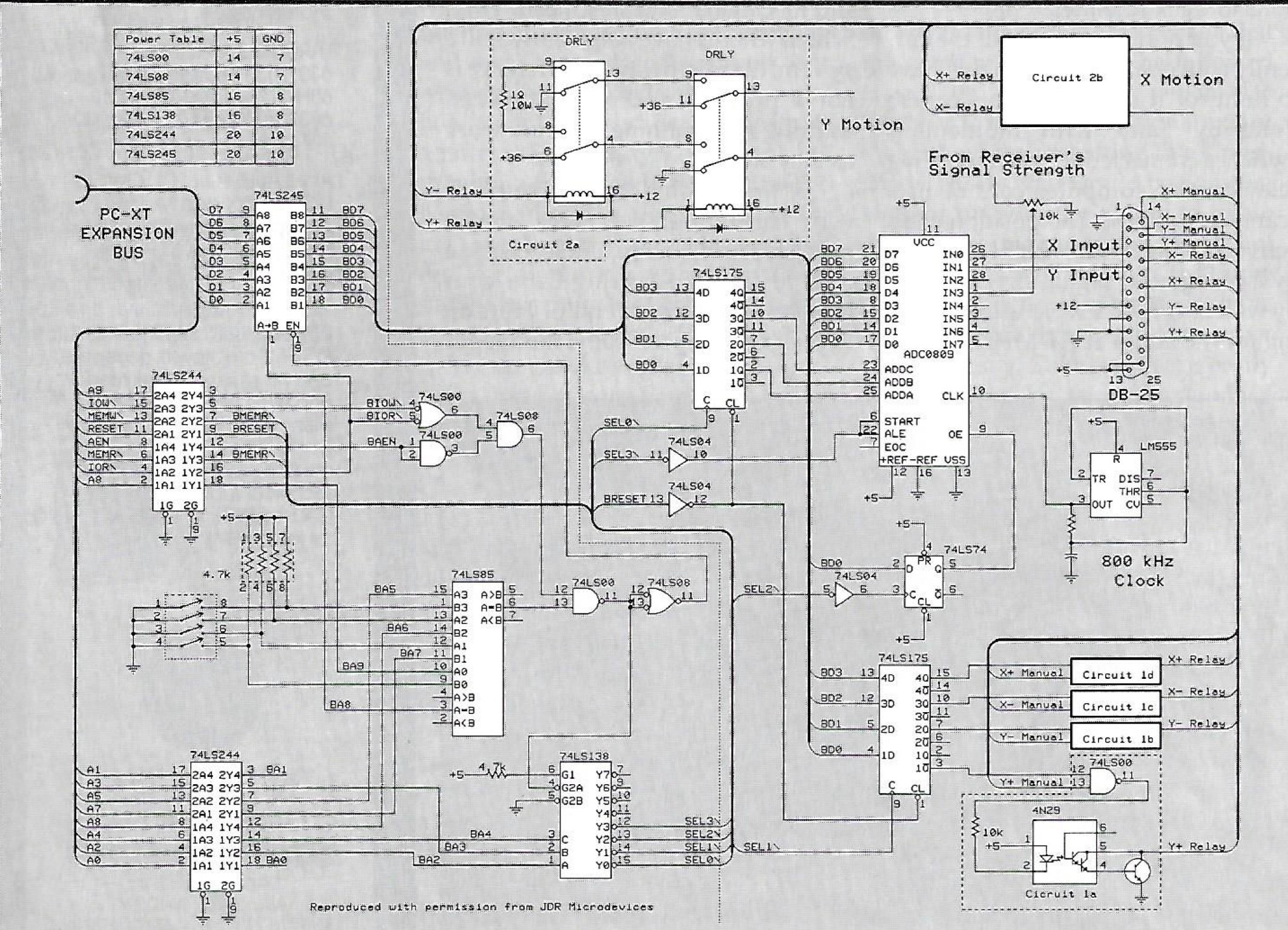
Actuators come in many varieties. The typical low-cost units used on home dish receivers use DC mo- tors and have either pulse or potentiometer position feedback. The activation of the DC motors is simple: apply 32 volts to the input leads to extend the arm, reverse the polarity to retract the arm. Figure 4 shows the relay circuit I use to control two actuators.
As mentioned earlier, feedback from the actuators can be either a series of pulses or a continuous voltage across a potentiometer - I prefer the potentiometer approach since it gives absolute position, whereas with a series of pulses you must remember exactly what position the arm is in, or recalibrate each time. The circuit in Figure 4 shows the complete controller. This design is used with a low-cost PC/XT clone motherboard, a CGA display, and one floppy disk drive, but provides all the necessary functions to track satellites.
If you don't know where the currently active satellite is, you will have to hunt for it manually. This can be done by hand with momentary switches connected to the controlling relays or by computer control in a scanning pattern. The position of an active satellite can only be determined by looking at RF signal strength, and by watching for a TV picture or listening for the audio at 7.4-MHz. My house happens to be directly in the path of a strong terrestrial microwave signal which causes false triggering and often shows a high RF signal strength when in fact no satellite signal is present. For this reason, a fully automated tracking program doesn't work well. If you live in an area that is free of microwave interference, you will be able to track each satellite and automatically hand off to the next one with little difficulty. In spite of the microwave interference, I don't have much trouble With automated tracking once I manually locate the satellite and lock onto it, but if the position of the satellite happens to be next to a strong terrestrial source, the tracking program can become confused and be dragged off into the microwave noise. Also, due to these hot spots in the sky, I can't run an automated X-Y scanning procedure to locate the active satellite. At SCOLA's site in Omaha, and at Lincoln High School where I have helped to install a system, the microwave interference is not a problem and the automated tracking and scanning software work as they should.
At first, finding the satellite can be very frustrating, but some simple guidelines will help. First, check a map to find the bearing from your location to the north end of Hudson Bay, Canada. Specifically, the apogee is always near 80 degrees West Longitude and 63 degrees North Latitude. Position the dish to the midpoint of its east-west actuator range. Find the offset from true north to the apogee location and aim the dish at that point. For the continental U.S., set the midpoint of the dish elevation range to be your latitude plus 30 degrees. In Europe, set the midpoint to be about the same as your latitude. Manually pan the dish, scanning through the entire "window" in four-degree increments or bands. With the receiver set to transponder 9 and audio subcarrier at 7.4 MHz, you should encounter at least a distorted picture and some sound. After finding maximum signal strength, you can adjust the receiving frequency and other parameters on the receiver for a clear picture.
One of the best ways to learn how the satellites move is to manually track them through one or more active loops. If the satellite is near apogee, you won't have to readjust the dish position more than once every fifteen minutes or so, bu if the satellite is starting back down toward perigee (moving higher in the sky), it will be accelerating and will require adjustment at least every four or five minutes. After you have determined the optimum range of pointing angles for your dish, you can adjust the actuator mounting brackets to allow for the optimum range of motion. Remember that each satellite will be in a slightly different orbit, so they won't always appear in the same place in the sky as another satellite.
One other complication: due to the parameters of the Molniya Orbit, these satellites recede in their orbits by about 4.5 minutes per day. This means that if you found the satellite at a certain point today, you would find it at that exact same point 4.5 minutes earlier tomorrow. Assuming that you are tracking the satellites automatically each day and everyday, the practical effect is that the hand-off times (when control is transferred to the next upcoming satellite) will be four and a half minutes earlier every day. Since this is a small change on a daily basis, the software will take it in stride, but if you happen to skip a few days or a week or two, you'll probably have to go satellite hunting again (unless you have a really good memory). I use my system a couple of times a week, and With a bit of practice, I have found that it takes me less than two minutes to find the currently active satellite, and in the worst case, perhaps five minutes. If you follow Molniya satellites for months or years, you will also discover that sometimes their orbits change unpredictably, due to the use of station-keeping thrusters. Just like geostationary satellites, atmospheric drag and gravitational forces will eventually alter an orbit and require some intervention. Also, whenever a satellite grows weak or fails, a new one must be launched, often with different orbital parameters. In January of 1988 one of the four satellites apparently failed. Normally a replacement is launched immediately, but for some reason this didn't happen until July. No direct statement could be obtained from the Soviet government, but some thought this meant they were discontinuing the use of the Molniya satellites; others had heard rumors that the replacement satellite and launch vehicle blew up on the launch pad and that no spare was available, causing the delay. In July the gap was filled, which was a great relief to those of us who enjoy tuning in to “the Other Side.”
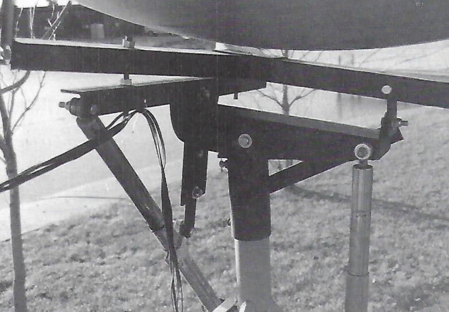
Photo 3: Close-up view of the modified polar mount.
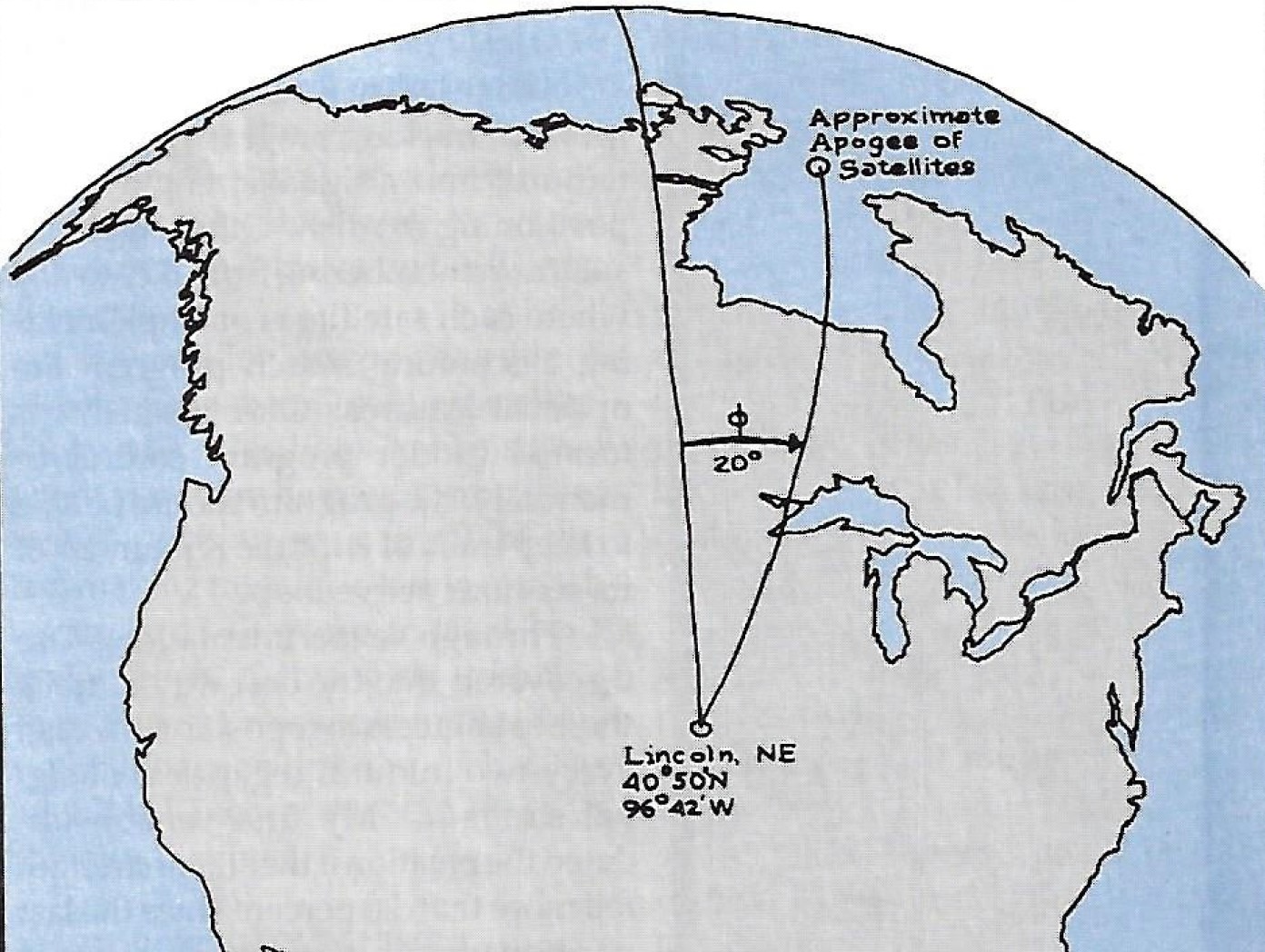
Figure 5: Determining the angle from the receiving antenna to Hudson Bay, Canada. Depending on your location, the dish should be aligned so that the center of its range of movement is offset from true north. For Lincoln, Nebraska this should be about 20 degrees east of north. For the cast coast, the dish should point due north. For southern California use a 30-degree offset and for northern California use a 40-degree offset.
THE SOFTWARE
The primary function of a simple Molniya tracking program is to maintain maximum signal strength by repositioning the dish. Other functions such as remembering from day to day where each satellite is or implementing a scanning search program are optional features. Once a satellite is located (under program control or manually) the program should be able to keep track of it for the remainder of its six-hour active loop. Through experimentation, I've discovered that the best way to track these satellites is to reposition the dish every two minutes regardless of signal strength. My first version updated the position if the signal strength fell more than 20 percent since the last position update, but due to terrestrial microwave interference, this technique was unreliable. Again, if you live in an area that is free of such background interference, this approach will work quite well. Every two minutes, my program moves the dish through a programmed search pattern—up, down, left, and right of the current position. The amount of movement depends on many things including the size of your dish and signal strength. The goal is to move the dish only enough to detect a change in signal strength, but not enough to fill the picture with static. The viewer should not be aware that the dish is moving. This type of adjustment involves changing the duration of relay closure. The search algorithm I use is shown in Listing 1. [Editor's Note: Software for this article is available for downloading from the Circuit Cellar BBS and on Software On Disk #10. For downloading and ordering infomation, see page 78.] This loop will move the dish in all four directions looking for maximum signal strength. The first pass is with a step size of 1.0—meaning the full relay closure time (maybe 300 ms), while the second pass sets the step size to half of this value for fine tuning. The dish movement routines move-up() , move-down(), move-left() , and move-right() must close the appropriate relay for a specific number of milliseconds. As mentioned before, the time delay used here must be determined experimentally depending on the type of actuator used. The GetRF() routine simply reads the analog-to-digital converter and returns an 8-bit value for RF signal strength. Dish position can be determined by reading the A-to-D converter channels 0 and 1. Positions can be stored each day and can be used to represent the X-Y position on a graphics display, making manual location of satellites easier if they are tracked on a regular basis. I've also added a GotoXY(x, y) routine to my package to quickly reposition the dish. The QuickBASIC code for GetRF() is shown in Listing 2.
Figure 4: The dish controller circuit for use with a PC-compatible. The ADC0809 8 - channel analog-to-digital chip was used to read both X- and Y-axis voltages which provide feedback about dish position, and to read the RF signal strength which is fed from the satellite receiver. Four output lines feed relay controls which are combined to produce X and Y actuator motor voltages. The DC motors are reversible depending on polarity of the 32-volt input.
EAVESDROPPING ON THE SOVIET BLOC
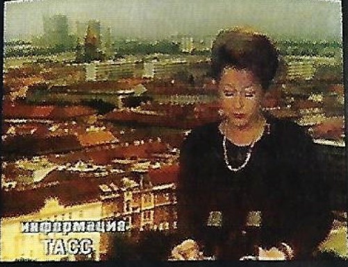
Access to Soviet television programming which is intended only for a domestic audience provides a rare opportunity to see the Soviet Union without the filtering that exists when material is selectively chosen for an American audience. It provides a view of the country and its people as they see themselves. Few people realize that the Soviets have their own version of TV ratings and market research, causing fierce competition among producers and writers to respond to the demands of viewers. Not surprisingly, the variety and quality of programs has increased during the Gorbachev era. The photos at the beginning of the article show some examples of Soviet TV programs. Although there are many news and current affairs programs, the national networks provide a rich variety of cultural programs from virtually every Soviet republic, along with sports, travelogues, game shows, exercise programs, documentaries, spy thrillers, World War II movies, concerts, children's cartoons...
Mark Dahmke is a consulting editor for CIRCUIT CELLAR INK. He lives in Lincoln, Nebraska and works as a consultant for the Lincoln Telephone Co. and Professional Research Consultants in Omaha.
Complete Molniya tracking systems are available from: SCOLA (Satellite Communications for Learning), California at 24th Street Omaha, NE 68178 (402) 280-4063
SCOLA also operates a subscription service to live or near-live international television via Telstar 303, including daily programming from a dozen countries including The USSR, China, Japan, Italy, Ger many, Mexico, Iran, and France. Teflon dielectric blocks for circular polarization conversion are available from: Chaparrel Communications 2360 Bering Drive san Jose, CA 95131 (408) 262-2536
Further reading:
The Satellite TV Handbook, Anthony T. Easton, Howard W. Sams & Co., Inc. ISBN 0-672-22055-5
Listing 1: the search algorithm moves the dish four directions looking for the maximum signal strength. The first pass is designed for most rapid movement, while the second is optimized for fine tuning.
step 2 = 1.0 ‘course position increment
step 1 = 0.5 ‘fine position increment
for step = step2, stepl
loop1: signal = oldsignal ‘ update signal
move-up(step)
signal = getRF() ‘get new signal strength
if signal > oldsignal then goto loop1
move-down(step)
loop2: signal = oldsignal
move-down(step)
signal = getRF()
if signal > oldsignal then goto loop2
move-up(step)
loop3: signal = oldsignal
move-left(step)
signal = getRF()
if signal > oldsignal then goto loop3
move-right(step)
loop4: signal = oldsignal
move-right(step)
signal = getRF()
if signal > oldsignal then goto loop4
move-left(step)
next(step)
end
Listing 2: This QuickBasic code determines signal strength by averaging four readings and then comparing the averages
FUNCTION GetRF()
CONST B = 3 ‘ADC0809 channel address for RF signal
CONST SEL0 = &h300 ‘Latch ADC address
CONST SEL1 = &h304 ‘Latch relays
CONST SEL2 = &h308 ‘Output enable ADC data lines
CONST SEL3 = &h30C ‘start ADC conversion
‘ get signal strength
FOR k 1 TO 4 ‘read it 4 times
OUT SEL0, b ‘set up adc0809 channel address
CALL WAIT (1) ‘wait a millisecond
OUT SEL3, O ‘start adc conversion
CALL WAIT (1)
OUT SEL2, 1 ‘output enable adc data lines
CALL WAIT (1)
siga = (INP(a + 20)) + siga ‘accumulate
OUT a + 8, 0
NEXT k
SUB GETXY(xc,yc)
‘get x, y coordinates
yc = 0
xc = 0
FOR k = 1 TO 2
b = 1 ‘data channel 1
OUT SEL0, b ‘load addr
CALL WAIT(1)
OUT SEL3, 0 ‘start conversion
CALL WAIT(1)
OUT SEL2, 1
CALL WAIT(1)
xc = xc + INP(a+20) ‘read result
NEXT k
xc = xc / 2 ‘average
FOR k = 1 TO 2
b = 0 ‘data channel 0
OUT SEL0, b ‘load addr
CALL WAIT(1)
OUT SEL3, 0 ‘start conversion
CALL WAIT(1)
OUT SEL2, 1
CALL WAIT(1)
yc = yc + INP(a+20) ‘read resuly
NEXT k
yc = yc / 2 ‘average
RETURN