
Scion Color System
by Mark Dahmke
BYTE Magazine, July 1982
In the November 1980 BYTE (see “The MicroAngelo Video Display,” page 196) I reviewed the Scion MicroAngelo graphics display—an S-100 board that provides 512 by 480 dot resolution. The board contains a Z80 microprocessor and 32K bytes of memory, making it one of the most powerful graphics displays of its class. It has only one limitation—no color or gray levels. Each dot out of 245,760 dots is either on or off.
Now, Scion has announced the MicroAngelo Color System, which consists of a set of MicroAngelo boards connected together through a color mixer or palette board. With more than one board contributing to the display, each dot or pixel (picture element) can be described by enough bits to specify a color or other intensity for each pixel.
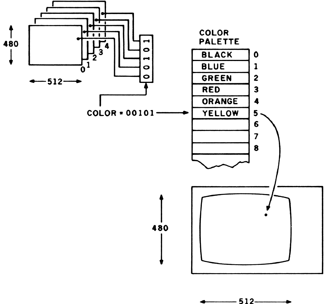
The color system offers unprecedented capabilities for its low price. Because each MicroAngelo has an on-board computer, you can send commands to each board and have them processed simultaneously. The palette board mixes the outputs of multiple (from two to eight) MicroAngelo boards by looking for the color value represented by parallel bits in the parallel MicroAngelo boards. In a two-board system, you could display 4 different colors; in an eight-board system, 256 different colors. Each color-palette entry is defined in red, green, and blue (RGB) components, each of which can range from 0 to 100 percent in 256 steps. This means that on a full system, you could choose 256 colors out of a palette of more than 16 million colors.
Figure 1 shows the hardware organization of the color system. The palette board must be present on all versions, but you can start with two MicroAngelo boards and work up to eight. A 20-conductor ribbon cable connects the boards to the palette board. Each MicroAngelo has its own Z80 running at 4 MHz and on-board firmware in PROMs (programmable read-only memories). The firmware can be either Screenware Pak I or Screenware Pak II, which offers the additional capabilities of region flooding, hardware and software test routines, split screen for separate alpha and graphics regions, firmware circle drawing, and macro definition allowing the on-board Z80 to draw frequently used shapes or objects. I will not spend much time describing the firmware features of the MicroAngelo; I suggest that you read my review in the November 1980 BYTE.
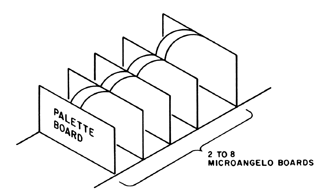
The Palette Board
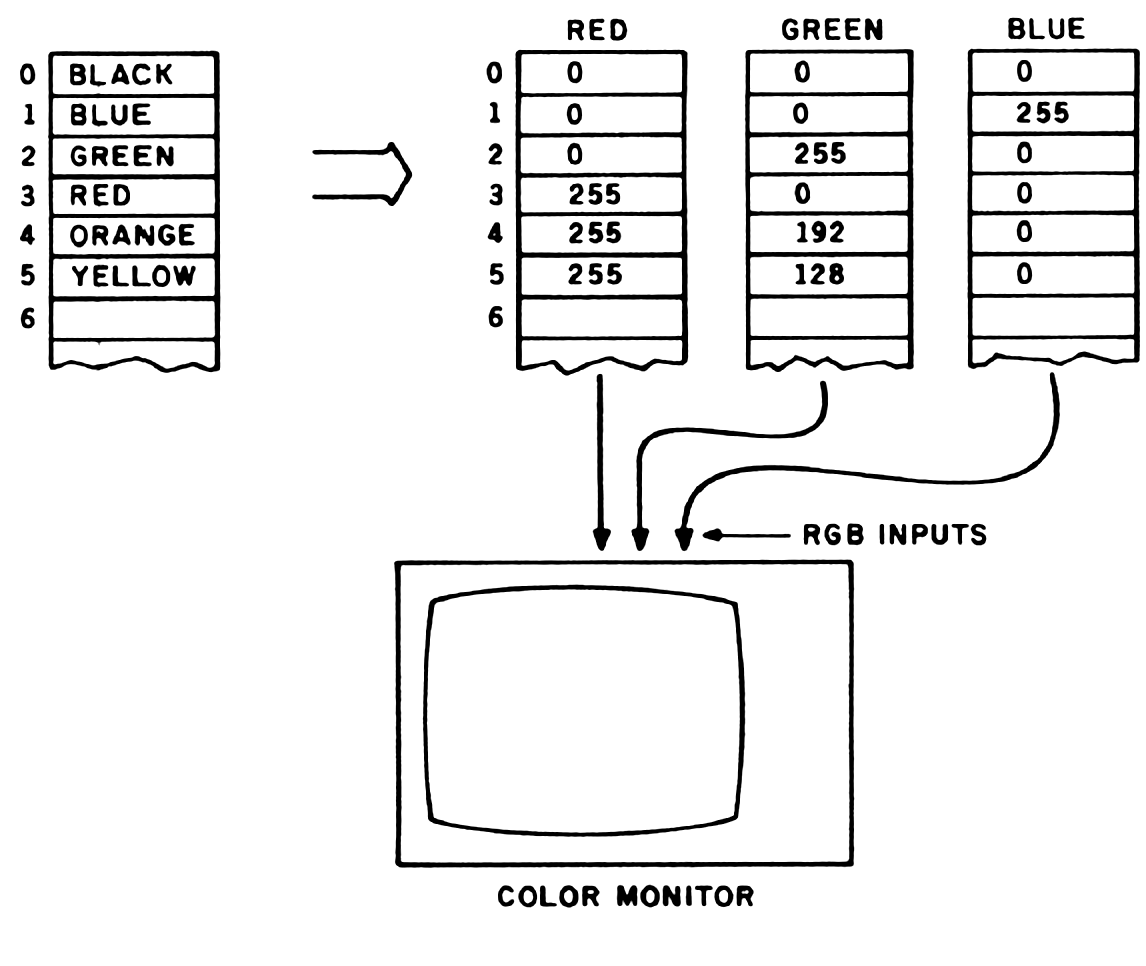
Figures 2 and 3 show how the palette board converts bitplane information into colors. The software must set the appropriate bits in the MicroAngelo boards so that the bits make up the number of the color-palette entry. When the display is generated, the palette board converts the number into separate red, green, and blue values, which are in turn sent to the RGB color monitor. The process is really quite simple and powerful. Note that the color of an object on the screen can be changed after the fact by simply changing the color-palette entry for that combination of bits.
Software and Firmware
As mentioned earlier, the Screenware Pak I and II PROMs are on board the individual MicroAngelo bitplanes. The system is very fast because each board receives its commands and executes functions such as drawing a vector or circle. A software package called Colorpak that manages these high-level functions is included. Colorpak is written as a subroutine library, callable from FORTRAN-80. It greatly simplifies the development of an application program. If you want to draw a vector in color number 3, you would code the following:
CALL CURCLR(3)
CALL GRCUR(100,100)
CALL VECTOR(120,150,-1)
The first statement selects color 3 (which was previously defined in the program). The second line moves the graphics cursor to screen coordinates 100,100. The third statement draws a vector from the graphics cursor location to 120,150. The -1 parameter tells the Colorpak to draw the vector in the currently selected color.
It is also possible to group bitplanes into “transparencies.” This is like having several windows or screens that overlap each other. For example, you could set up two transparencies with four bitplanes, allowing 16 colors per transparency. One transparency could have a grid on it, while the other could display a floor plan for a building. The two transparencies can be displayed separately or overlaid in several ways. First, you could display the floor plan on top of the grid, or for measurement purposes, you could put the grid on top. This can be changed dynamically by subroutine calls without redrawing the image.
You can also decrease the intensity of a transparency to any percentage of full intensity. Whenever there are multiple transparencies, the color palette is automatically configured to display the color that has precedence—the color from the transparency that overlays all others. You can mix colors that overlap, creating a new color. One possible use for this feature would be in circuit-board layout. The wiring diagram for a circuit could be displayed, with the cross-over points highlighted in a different color.
The hardware also allows winking bitplanes. When configured to wink, the display will alternate between two colors about every second. This feature also could be used to highlight information on the screen.
The Color Editor
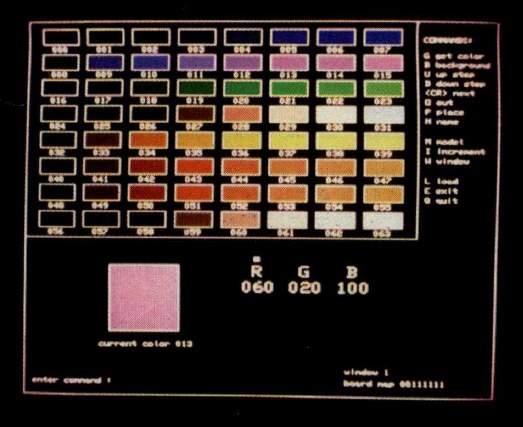
Defining an organization of transparencies and colors can be difficult at best. It is very handy to be able to see the colors as you mix them on the palette. Scion has generously provided a color editor that aids in the design of an application. The color editor is a large program that draws a set of one-inch-long boxes on the color display. A small command language allows the user to vary each of the RGB components of each palette entry to see the resulting colors. When a color has been selected, it can be stored in one of the 64 palette entries. Actually, there are up to 256 palette entries (if you have eight bitplanes), but only 64 are displayed at one time. Photo 1 shows the color editor with a typical palette of colors.
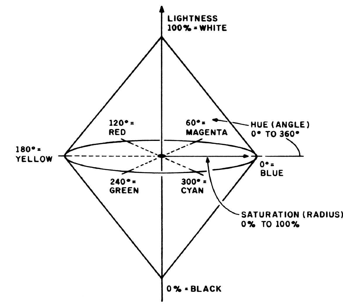
The editor normally uses the RGB method of building and mixing colors, but the HLS (hue, lightness, saturation) model can also be used. Figure 4 shows the topology of this model. At first it may look quite confusing but is really a useful model. Hue is measured in degrees, from 0 to 360. Blue is at 0, red is at 120, and green is at 240. Note that all of the primary additive colors are at 120-degree increments around the circle. Yellow appears at 180 degrees. Lightness is measured in percent, from 0 to 100. Zero percent is black, regardless of the hue and saturation values, and 100 percent will produce white. Saturation is also measured from 0 to 100 percent and is really a measure of the chroma or amount of color visible. It is graphically represented in figure 4 as the radius of the color circle.
Colorpak Functions
Working with Colorpak is like working with a combination of a Tektronix graphics terminal and the IBM 2250 graphics display. Most of the subroutine calls are obvious, e.g., “CALL VECTOR” and “CALL POINT,” and the color system requires a fair amount of initialization. You must do one of two things: use the color editor to define a set of colors and one or more transparencies, or use Colorpak to define the same. With the color editor, the task is quite simple. To load a screen organization and color palette, you would code:
CALL GETSYS('FILENAME',0)
where “FILENAME” is the file defined by the color editor, and 0 indicates that it is on the current disk drive. If you wish to do it the hard way, the following sequence might be used:
CALL CINIT(112,3,240,225,208,0,0,0,0,0,2)
CALL DEFTRN(1,3,0,0,0,0,0,0,0,0)
CALL PUTCLR(1,1,0,0,255,0,0,0)
CALL PUTCLR(1,2,0,255,0,0,0,0)
CALL PUTCLR(1,3,255,0,0,0,0,0)
CALL PUTCLR(1,4,255,192,0,0,0,0)
CALL PUTCLR(1,5,255,128,0,0,0,0)
CALL ERASE(1,1)
The first statement initializes the color system and defines it as having three bitplanes at decimal I/O (input/output) port addresses 240, 224, and 208. The last parameter is 2, which tells the Colorpak that you are using Screenware Pak II. The second line defines a transparency structure with one transparency of three bitplanes. The next five lines assign colors to the palette. This particular initialization will make the system look like the examples in figures 2 and 3. The last call is made to erase transparency 1. Colorpak has some useful subroutines such as FLOOD, which will fill a bounded region with the currently selected color. The fill algorithm is in firmware, so it runs very fast. FADE will fade out a transparency to a percentage of its full brightness, and FUSE will fuse colors in overlapping transparencies. MOVTRN allows you to change the display precedence of transparencies.
As with the MicroAngelo video display, cross hairs and a lightpen interface are available.
A Real-Life Application
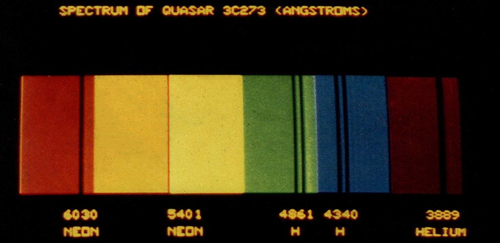
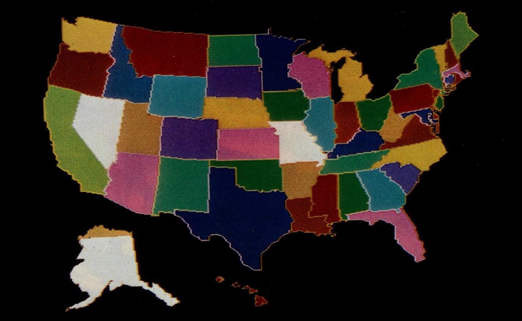
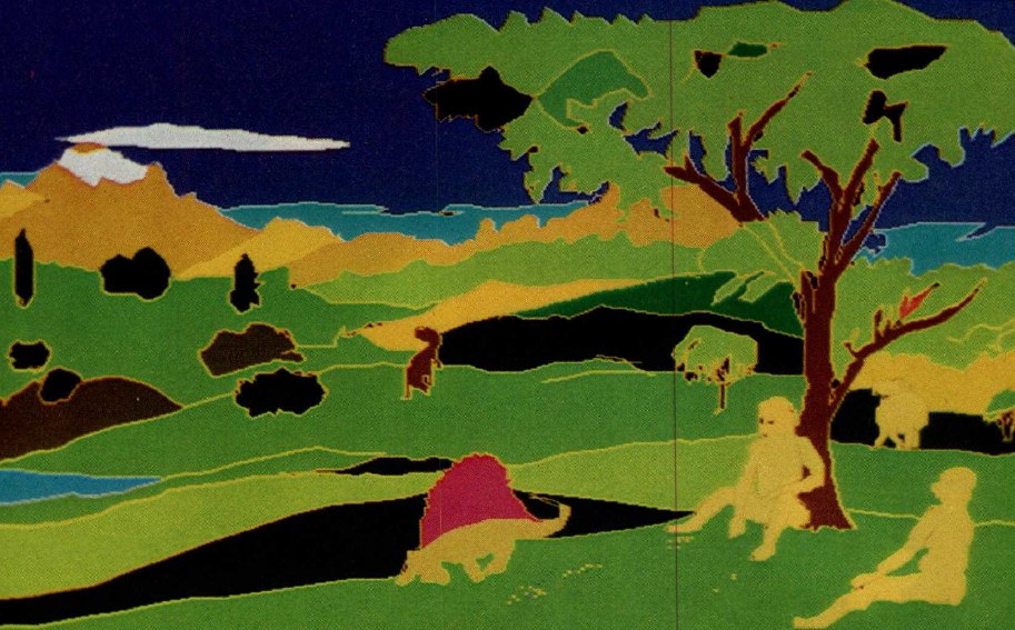
After trying out the samples included on the CP/M distribution disk, I pulled out my old favorite—the three-dimensional model of the galaxy (see “A Simulated View of the Galaxy,” April 1979 BYTE, page 66). I decided to include stellar magnitudes (brightness) and spectral color for a better effect. I downloaded the FORTRAN program from an IBM System/370 on which I had been running it and compiled the program on my CP/M system. I added the initialization calls, using a color library I defined with the aid of the color editor. Photo 1 shows the resulting color palette, which has seven different colors, each with eight intensity levels. In astronomy, the colors of the stars are categorized as O, B, A, F, G, K, and M. These are very blue, blue, green, white, yellow, orange, and red, respectively. (A second white row appears at the bottom.) Other samples of color graphics are shown in photos 2, 3, 4, and 6.
Conclusions
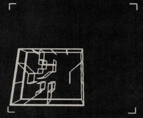
I have had the Scion Color System for several months, and I really don’t want to give it up. It is one of the most convenient graphics systems I have ever worked with. The best test I could give it was my star map program, which used almost all the features of the system. The fact that I downloaded the FORTRAN program from an IBM computer and modified it to run on the Scion system in less than three hours also says a lot for the system. BYTE author Ken Livingston and I also downloaded Ken’s architectural three-dimensional modeling system. It took one evening to change the graphics interface and recompile it on my CP/M system, then a few more hours to fine tune it. After that we were able to generate wire models of buildings and project different views of them. Photo 5 shows a sample of Ken’s program.
At a Glance
Name
Scion Color System
Type
512-by-480-resolution color graphics system that can display up to 256 colors out of a palette of more than 16 million colors
Manufacturer
Scion Corporation, 12310 Pinecrest Rd., Reston, VA 22091
Price
Color System with two MicroAngelo boards (4 colors), $2,495; with six boards (64 colors), $6,495; with eight boards (256 colors), $8,495; for Screenware Pak II, add $400, plus $40 for each extra board beyond the first. A fully configured eight-board system with Pak II would cost $9,175. RGB color monitors are available at $2,495.
Features
Up to 256 colors on one display with a full eight-board system; a light pen is optional. Each board has a Z80 running at 4 MHz (which can run at 6 MHz), 32K bytes of main memory, room for 8K bytes of EPROM memory (used for Screenware Pak I or II), and a 512 by 480 dot display. Palette board has RGB generation circuits and high-speed look-up memory for palette selection.
Firmware
Full firmware to generate vector graphics and characters; high-level commands sent via parallel ports. Functions include drawing vectors, plotting points, and generating characters (normal or double size; rotation is also available). Screenware Pak II can flood a region with color.
Software
Several CP/M-compatible programs are available, including COED, a color editor program that displays a palette on the screen and lets you build colors from either the RGB or HLS models. A FORTRAN-compatible subroutine library (Colorpak) is provided so that high-level commands can be executed without having to understand or program the hardware. Three sample programs are also on the distribution disk, as well as the source listing (in FORTRAN) for the Colorpak subroutine library.
Computer Needed
Any S-100-compatible computer or any computer that has an S-100 bus adapter. Although the Color System uses a Z80 microprocessor, the host processor does not have to be Z80- or 8080-compatible. If you plan to use the COED and Colorpak software, you must be able to run it with CP/M and FORTRAN-80 (or a similar language). You will also need a wide-bandwidth (15 MHz or more) RGB color monitor. Monitors are also available from Scion.
Documentation
A 130-page Color System manual is provided along with a pocket reference card for the Colorpak subroutine library calls and the MicroAngelo hardware manual (80 pages). Documentation is adequate but not exceptional.
Audience
Anyone requiring high-resolution color graphics on an S-100 system.