
I wrote this article in the spring of 1979, based on work I'd done in 1977 and 1978 while I was in college and participating in an engineering cooperative education program at the University of Nebraska. I was on a very limited budget and was trying to make the best use of the hardware I already had, and at the time I was reading everything I could find about multiprocessing and multitasking, which was mostly based on the IBM 370 architecture. I just assumed that it would eventually be implemented on micros in much the same way as on mainframes.
I had it all worked out and had started writing code to make my 8080 and Z80 processors talk to each other and then a new project (and urgent) came along - a speech synthesizer system for my friend Bill Rush (for more information see this article. The target development system was a Poly 88 - a small form factor Z80 S-100 system. But we still hadn't acquired a floppy disk drive or controller and I needed to get started on the software design, so I repurposed the parallel port interprocessor communication idea to bootstrap the Poly 88 from my homebuilt computer. By the summer of '79 my homebuilt computer had an iCOM floppy drive, text editor and Z80 assembler. I wrote the code for the synthesizer on it, ran it through the assembler and then a small boot loader EPROM on the Poly 88 read bytes from the parallel port and loaded the program into memory. It was slow but I got a lot of work done while the rest of the hardware was still being pieced together.
This article appeared in Bits and Pieces Volume 4: Programming Techniques, published by BYTE Books in 1979.
Introduction to Multiprocessing
My personal involvement with microprocessors began in 1975 when I constructed an 8008-based microcomputer. Over the years, I have added to a Martin Research 8080 board so that I now have 32 K bytes of memory, dual floppy-disks, a modem, two serial ports, and 30A power supply—all with an assortment of S-100, Martin Research, and custom wirewrap boards. The system works as-is, but it has fallen prey to the troubles of any system that has grown haphazardly to its limit. The S-100 interface works properly with the existing boards, but I must be extremely careful when adding any new boards as they may not run on my bus. I also can't run interrupts, direct memory access (DMA), or dynamic memory cards. Since I now have the money to expand, I could go out and buy a new mainframe and move all the S-100 cards over to it. However, then I lose the Martin Research boards which include both serial ports, the keyboard interface, 8 K bytes of memory, and a PROM board. I could sell them and convert to S-100, but why get rid of perfectly good hardware?
The answer to my dilemma is multiprocessing. Multiprocessing means running two or more processors in either a loosely or tightly coupled configuration. Loose coupling means that the machines are physically tied together via machine-to-machine input/output (I/O) ports, sharing the work load on a program-by-program basis. Figure 1 shows such a system, where each processor has its own main memory but shares the disk drives. On large machines programs are generally read in on cards (or from a terminal) and kept on disk in a queue (ie: waiting line) until the processor is able to work on them. Both processors can read jobs from the queue and begin executing them. As shown here, job A has requested to be run on processor 0, and so has job B. Job C wants to be run on processor 1, but job D has no preference. In the last case, job D will run on the processor that gets to it first. Once in a given processor, the job remains there. From the user's standpoint, the system will appear to run twice as fast as a single machine. Note that the individual jobs are not running faster, but since two jobs may run at the same time, more work is done. A commonly used term for this arrangement is shared spooling or shared queueing. The primary advantage over two independent processors is that both halves of the multiprocessor can access the same files on disk.
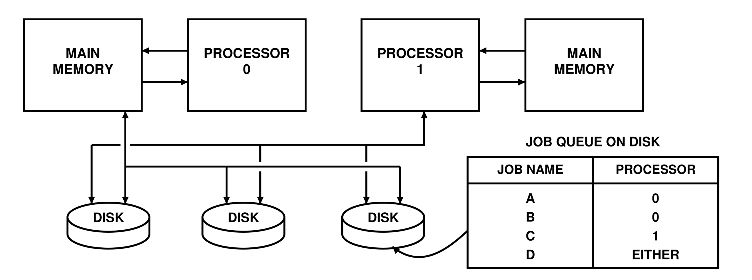
Figure 1: A loosely coupled multiprocessor. Each processor has its own non-shared main memory, but both processors share the disk drives.
Tight Coupling
Tight coupling involves extra hardware that allows both processors to access the same main memory. Figure 2 shows a typical tightly coupled multiprocessor. The memory can be shared in a number of ways. First, the expensive and difficult-to-obtain multiport memory chips can be used. These memory chips have two sets of all address, data, and control lines. Both processors can access the same byte at the same time. In a large installation, multiprocessors are used to split the workload on a time-slice basis within a program. Hence a user's program may bounce back and forth between processors as the system attempts to run the two highest priority tasks (ie: programs) at all times. The second approach involves direct memory access. Many microcomputers allow DMA, but very few people use it. Consider what happens on a typical microcomputer when two processors are on the bus and one begins a memory access. If it gains control of the bus, the other processor must be in a hold state, and vice versa. DMA may be useful for some I/O data transfers (ie: disk or tape at high speeds) where the microprocessor cannot keep up, or in graphics display hardware that accesses external memory, but DMA serves no useful purpose in a multiprocessor configuration. What good is it to have two processors when only one can perform at any instant? On a 6800 microprocessor, one can complement the clocks and run two processors on the same bus without conflicts, however I have not seen it done commercially.
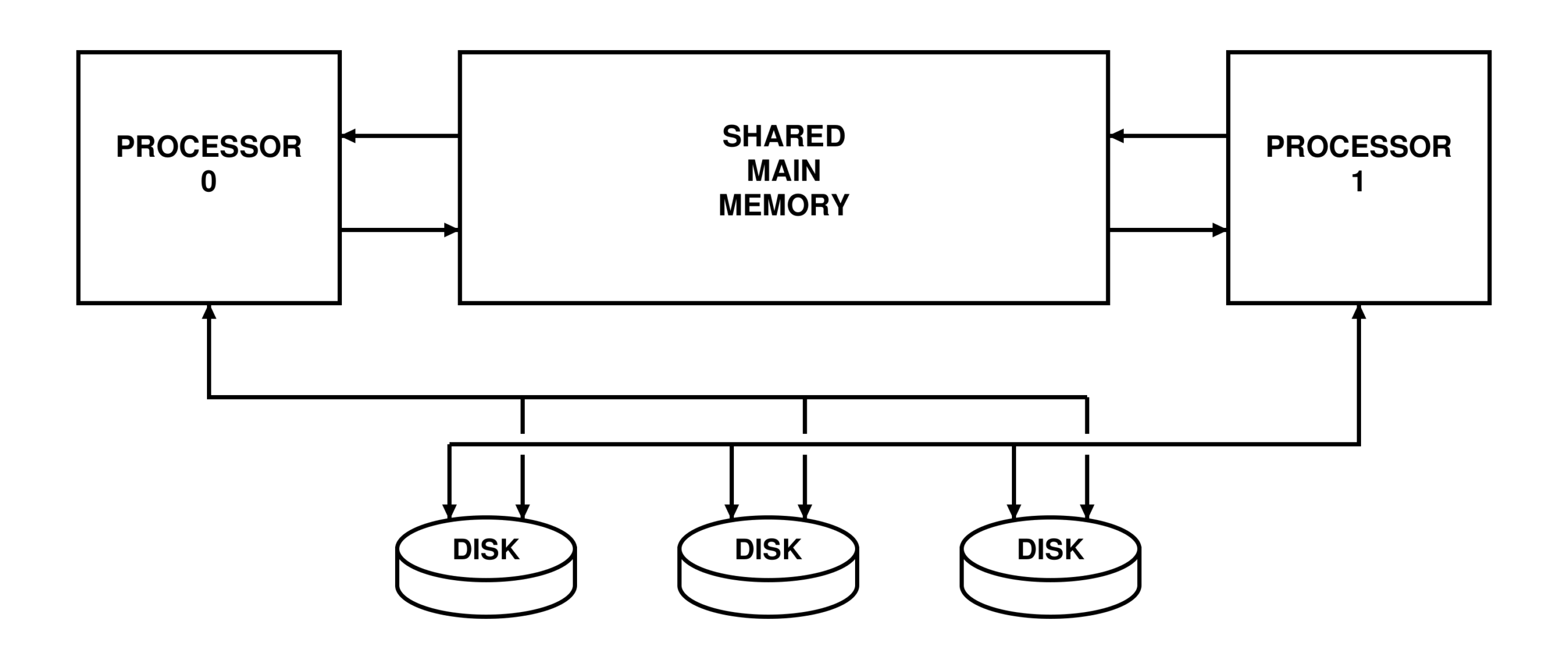
Figure 2: A tightly coupled multiprocessor. Both processors share the same main memory and also share disk storage.
Shared Memory Blocks — a Compromise
Perhaps direct memory access isn't the answer, but it would be convenient to have shared memory which both machines can access. Several minicomputers on the market already use this scheme. In figure 3, both processor 0 and processor 1 have 64 K address spaces, but each one has its own area from the 8 K boundary up to the top. The bottom 8 K of memory is either built with multiple-port access technology or resolves references by sending wait states out to the other processor while servicing a request. This way, the DMA access is cut to a minimum because a given processor will only be held up for a small percentage of the time.
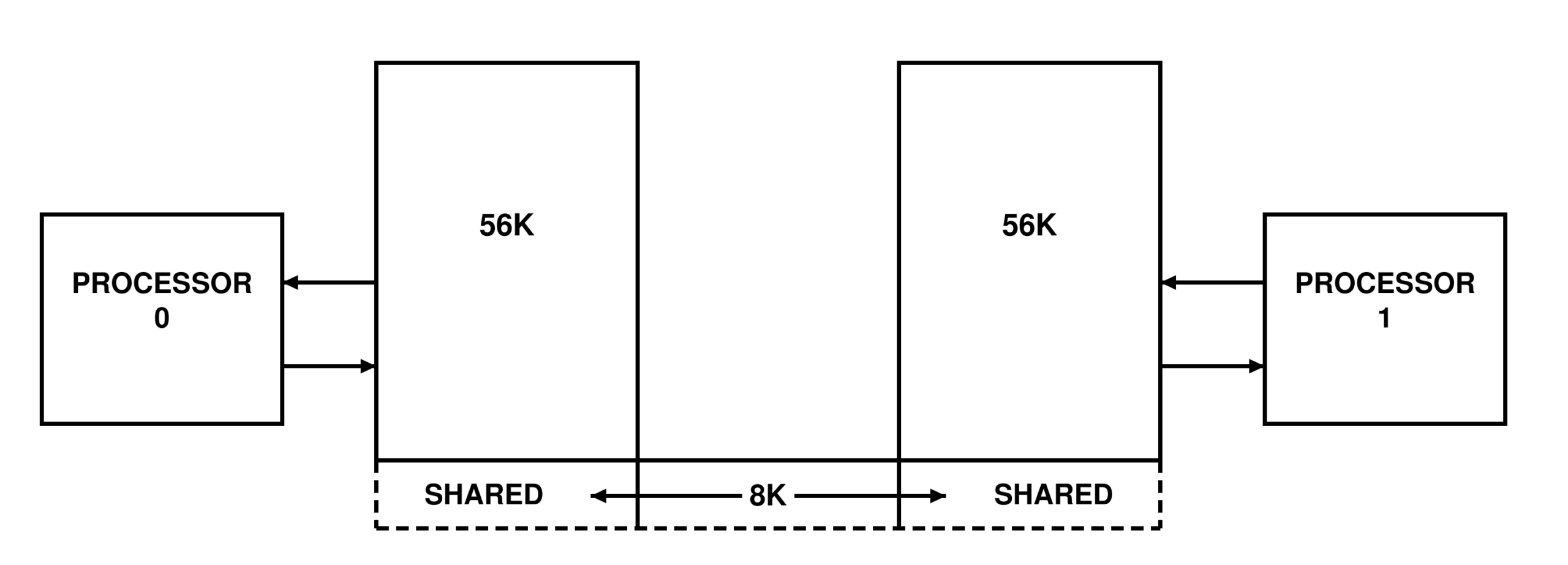
Figure 3: A tightly coupled multiprocessor with partially shared memory. Each processor has its own memory (up to 56 K in this example) but both share the bottom 8 K. Special hardware must be provided to resolve the conflicts in bus usage when accessing the bottom 8K block. Typically, if both processors try to access the 8 K block at the same time, the hardware will send out wait states to one processor while servicing the other.
Nonsymmetrical Machines
Until now, I have considered only those machines that are symmetrical; that is, capable of executing identical programs on either processor. Other possibilities do exist. Most hobbyists try to keep up with the latest technological advances by playing musical hardware—buying a Z80 to replace the 8080, which replaced the 8008, and so on. In my case, I have wanted to upgrade to a Z80 for some time, but am reluctant to change my existing system. I plan to leave the byte oriented devices (ie: keyboard, video board, modem, etc) on the 8080 Martin Research system and move the ICOM floppy-disk controller and 24 K bytes of memory over to the Z80. The two systems will operate in a loosely coupled environment with shared I/O as a compromise between fully loose and tight coupling. This involves running two full handshaking parallel ports between the two processors. (See figure 4.) In this arrangement, the old processor acts more as a slave than as a second master. One of the advantages of this configuration is that the disk drives are on one system and the other slow I/O devices are on the other, giving the effect of overlapped processing. Most floppy-disk interfaces are processor intensive; they demand exclusive use of the processor until the input or output operation is complete. In some cases, the disk may be tied up for as much as a minute at a time, forcing the programmer to wait.
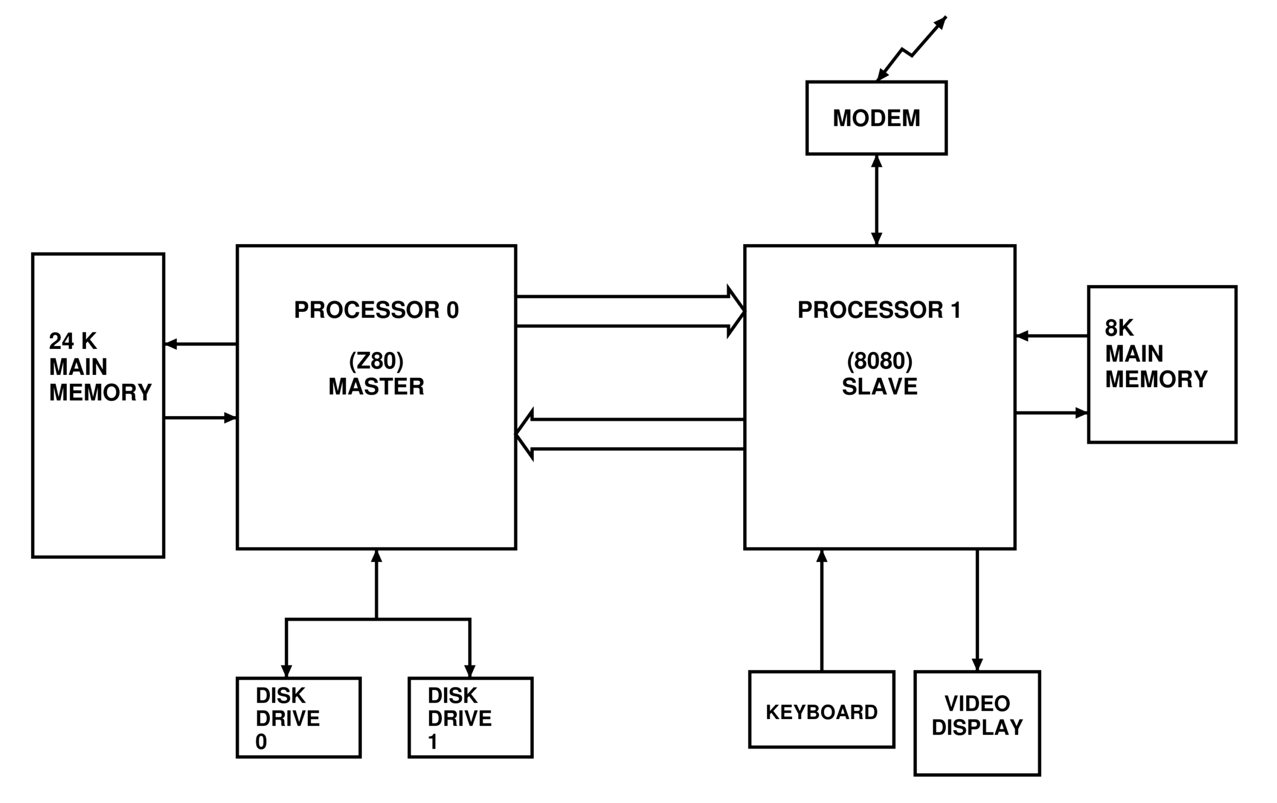
Figure 4: Master-slave configuration to be used in the author's system. Processor 0 owns the disk drives, and processor 1 owns all other I/O devices. The two parallel ports between processors 0 and 1 are for I/O communications. Processor 1 will be acting as a slave I/O processor, and will receive its commands and data from processor 0.
In the consulting business, personnel time is a far more valuable commodity than machine time. Having a slave I/O processor attached to the large machine is practical because the user can continue typing while waiting for the disk or any other time-consuming operation to finish. When considering the loosely coupled master-master or master-slave arrangement, it becomes clear that the two processors must communicate with each other at a rather high rate. It is assumed that the majority of the interprocessor communication will be I/O related—that is the master processor will load its I/O burden onto the slave processor. IBM calls the slave processors channels; some other manufacturers call them peripheral processors. Generally, a peripheral processor is somewhat more intelligent than a channel. There is a great deal of ambiguity in the terminology. No clear-cut definitions have been made—or are likely to be made in the near future. Depending on the sophistication of the controlling software, an auxiliary processor might resemble a channel, a slave processor, or an attached processor (ie: a second master processor that is oblivious to the outside world) capable of executing the same instructions as the master processor.
Interrupts
In microcomputers, there are several ways of alerting the processor that a device needs to be serviced. The most common method is that of priority-based interrupts. In this case, hardware is built into the processor to halt activity on command and transfer control to a predesignated service subroutine. Later, control is returned to the original program. Another method is to simply poll each device (ie: check a status bit to see if anything needs service). Polling requires processor time and implies that the program has the necessary machine code to handle the polling and that the code will be executed periodically. It becomes obvious that interrupts are simpler to handle, but there are other complications. Most disk-drive controllers cannot tolerate interrupts. If you interrupt a disk data transfer, it may be impossible to recover properly. There are several other reasons for not running interrupts, but I will not pursue them here.
Hardware for a Loosely Coupled Multiprocessor
Loose coupling is relatively easy—all that is needed is a set of parallel or serial ports with handshaking, one going in each direction. (See figure 4.) This will allow a single path for byte block transfers between machines. On my system, however, I would like to hook several devices to the slave. It would be wasteful to run a parallel port for each device, since the processor can only read or write to one at a time. So why not send along a device code or device address in parallel with the byte being sent across? (See figure 5.) That way, the slave can poll the port and can use the device code to determine what to do with the byte of data. This approach is very similar to a common technique called time-slice multiplexing, where the processor's attention is divided equally among requesting devices. For example, device code 0 may be used for keyboard input, device 1 for console output, device 2 for a modem (ie: dial-up), and so on. In order to run interrupts, the same bus structure can be used, but the data-ready line (in figure 5) will generate an interrupt. The interrupt routine will read the device code and determine which routine to go to for processing the incoming data.
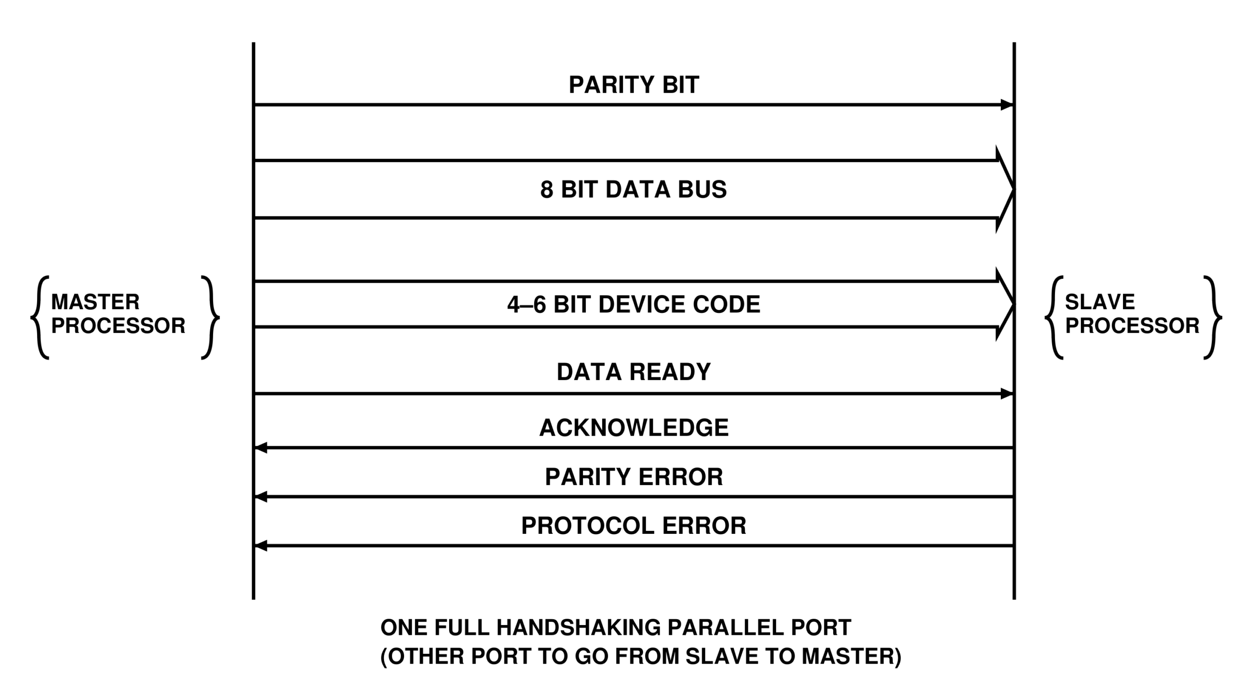
Figure 5: Anatomy of the parallel port. Along with the 8 bit data bus, a 4 to 6 bit device address is sent. This allows the bus to be time-multiplexed so that many devices may share the port.
Software for a Loosely Coupled Multiprocessor
After years of software development, I have learned that there is both a quick and dirty way to do something, and a clean and organized way. It is always easier to write quick and dirty software because it is initially the least time-consuming. But in the long run, it is far more difficult to modify. Clean code requires some additional thought and planning but saves a lot of effort when making changes. For most purposes, it seems that elegance and flexibility go hand in hand. In this section, I will outline and discuss an elegant approach to the I/O slave multiprocessor configuration previously described. First, I assume that the slave processor has many input and output devices attached to it and that the master will use the two parallel ports to communicate with all of these devices. The slave will have to have subroutines in order to work with each device. Another assumption I am going to make involves time multiplexing. Figure 6a shows how the port may be multiplexed, with the device code changing as successive bytes go to different devices. The unit time interval for a byte going out on the port is defined by the duration of the handshaking sequence. Figure 6b shows the timing of signals on the port. Note that the acknowledge line releases the port for another transmission. With this configuration, bytes destined for many different devices may be mixed on a byte-by-byte basis. How are they separated on the receiving side? Now programming and design philosophy become important. The simple solution would be to write a top-down modular structure. For most purposes this would be quite sufficient. But what would happen if we had a multiple byte protocol for one or more of the devices? Perhaps the console display routine has provisions for an addressable cursor and requires 2 bytes of data in succession after the command byte is sent (command, line number, column number). Can the next 2 bytes simply be read from the port? Remember that the port is being multiplexed; the next 2 bytes might have a different device code. The top-down technique may work well for a nonmultiplexed port, but runs into real problems when the port is multiplexed.
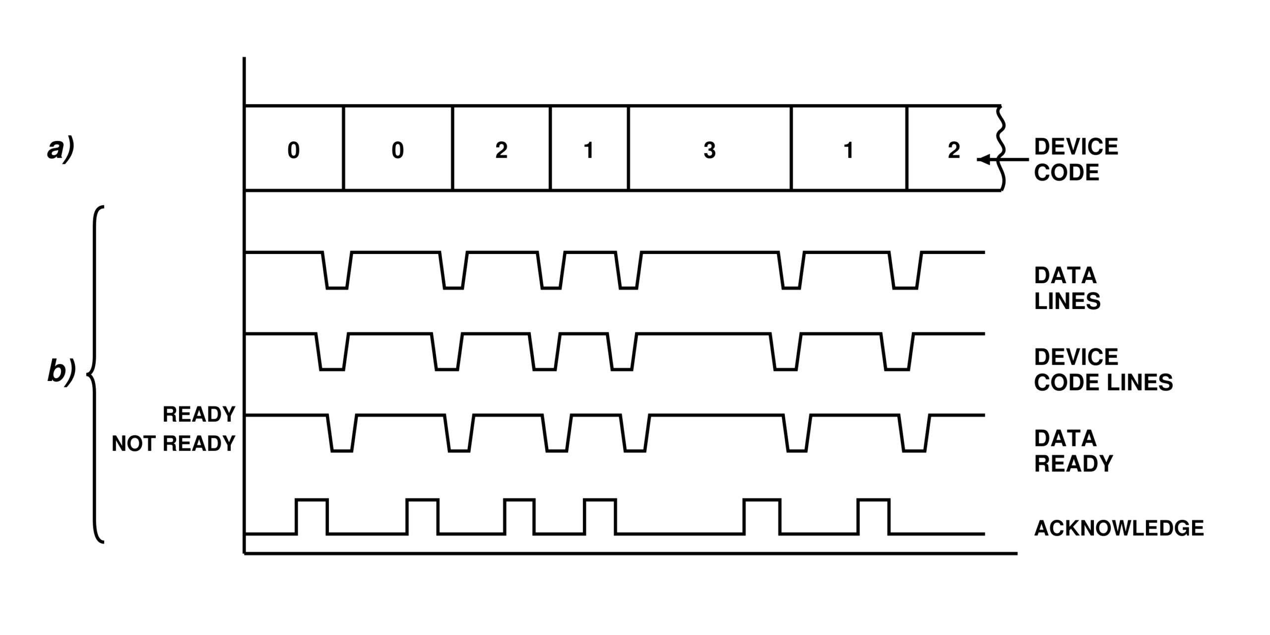
Figure 6: Port timing characteristics. (a) shows the byte and device code timing. (b) shows the signal timing of (a). When data ready becomes valid, the destination processor can read the data and do the error checking. When it has done this, it will send back an acknowledge, which will release the port for another transfer.
Coroutines
I would like to introduce a new concept before going on. Most people are familiar with subroutines—whether in FORTRAN, BASIC, Pascal, or assembly language, subroutines all do the same thing: they allow frequently used segments of a program to be referred to without duplicating the segment each time it is needed in the program. In figure 7, subroutine A is called twice, but after the return instruction is executed in subroutine A, control is passed to the instruction immediately after the last instruction executed in the main program (namely, the call A instruction). No matter where subroutine A is called the return instruction reloads the old address and continues where the main program left off. Coroutines are similar to subroutines, but they do not return to the old address as in a subroutine. In figure 8, control appears to be oscillating (ie: flipping back and forth) between programs A and B. Whenever the coroutine is called, it returns to a point just after the last executed instruction of the other program. This in effect is a crude form of timesharing. A more general form of this mechanism is called multitasking or multiprogramming. A thorough discussion of multiprogramming can be found in “Introduction to Multiprogramming,” also in this book. Multiprogramming gives us a clean mechanism for handling a time-multiplexed port. A main program or task is set up for each device. A generalized coroutine call is written that has a table of tasks and where each one left off when it encountered a coroutine call. The supervisor program, which includes the coroutine and task-switching routines, does the polling and, upon reception of a data-ready flag, will read the device code and look through the device assignment table. This table indicates which task should receive the byte of incoming data. The supervisor reactivates the specified task by loading up the task's old stack pointer and popping all registers (which are saved when the coroutine was called) off the stack. The reactivated task then reads the byte and performs whatever functions are required. This design is useful because it allows multiple threads of program logic without mixing them unnecessarily. Each task can be written independently of the others, without any register usage conflicts.
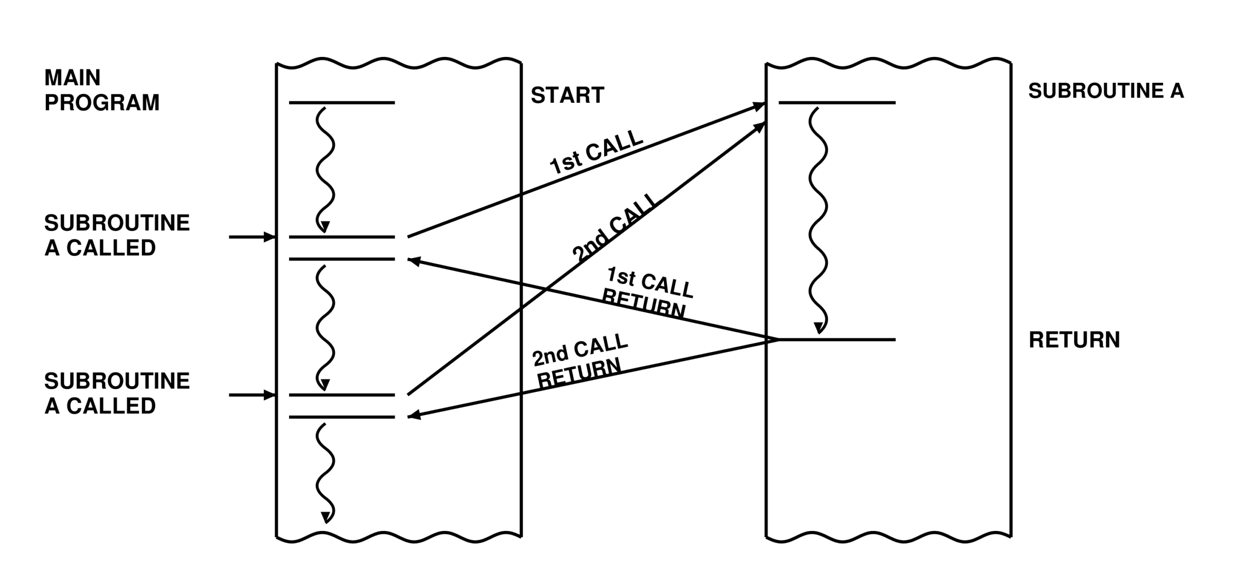
Figure 7: Flow of control when using subroutines. When subroutine A is called, the hardware in the processor must save the current value of the program counter so it can be restored when the subroutine finishes. Thus a subroutine can be called from any point in a program and will return to the instruction immediately after the subroutine call instruction.
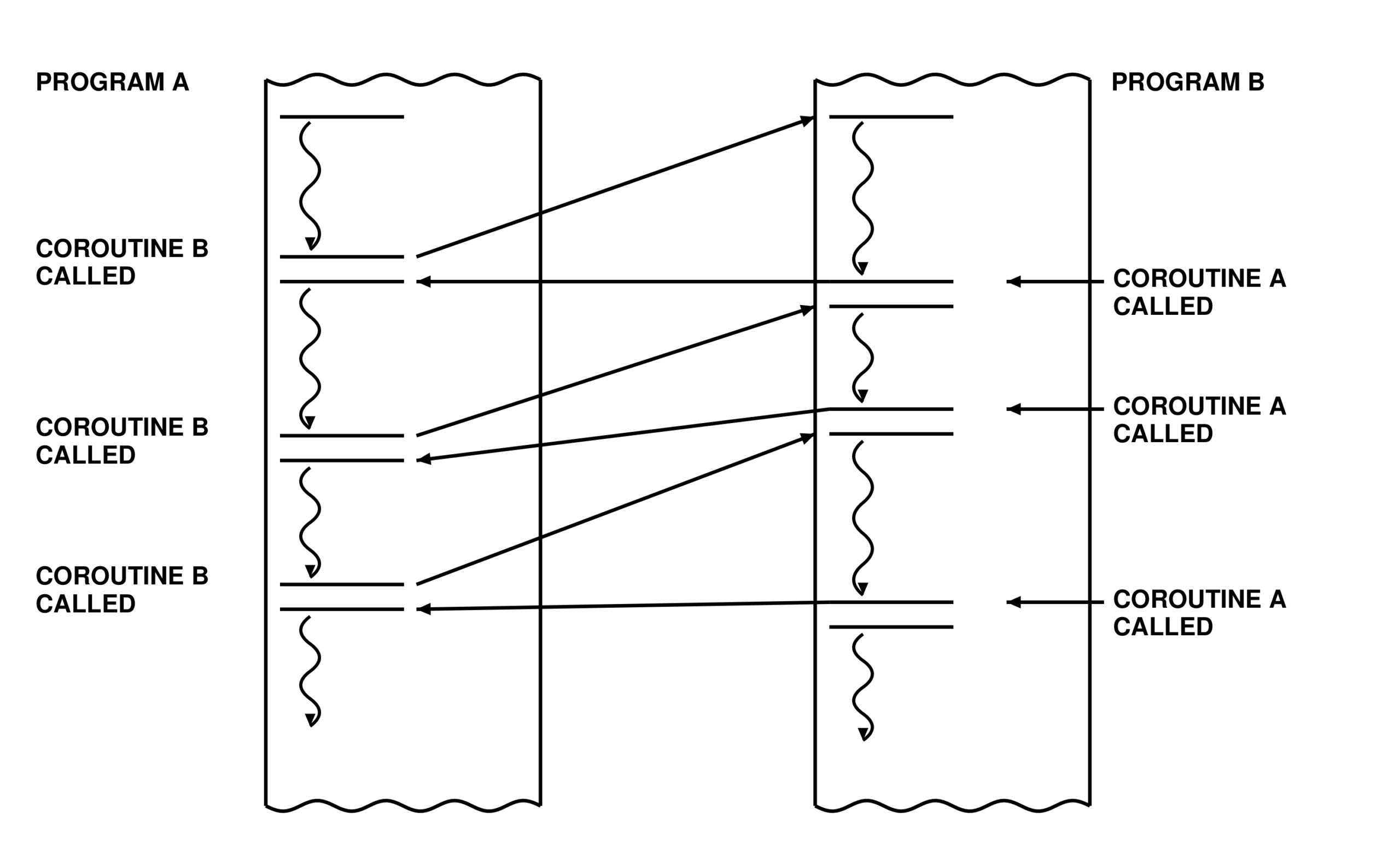
Figure 8: Flow of control when using coroutines. When coroutine B is called, control is passed to B. In B, when coroutine A is called, control is passed back to A to the instruction just after the first coroutine call instruction. Hence control appears to be flip-flopping between A and B. This is representative of a crude form of timesharing or multitasking.
Control Blocks and Tables
Earlier I mentioned that several lookup tables are used to determine which task should be given control.
The first control table is called the channel-status table or CHST. (See figure 9a.) Entries in the CHST have a byte for the device code, a task-assignment byte, and a status byte. If the device codes are put in ascending order, the device-code byte may be eliminated, saving a few bytes. The status byte includes a bit indicating whether the device code channel has been opened (ie: ready for service) or not. If it hasn't and someone tries to use it, a device error will be generated. Another bit in the status byte indicates whether the device code is defined or not. This is analogous to the open/close bit, but defines whether or not the device exists; if this bit is cleared, the device cannot be opened. Two other bits in the status byte define whether the device is to be used for input, output, or both.
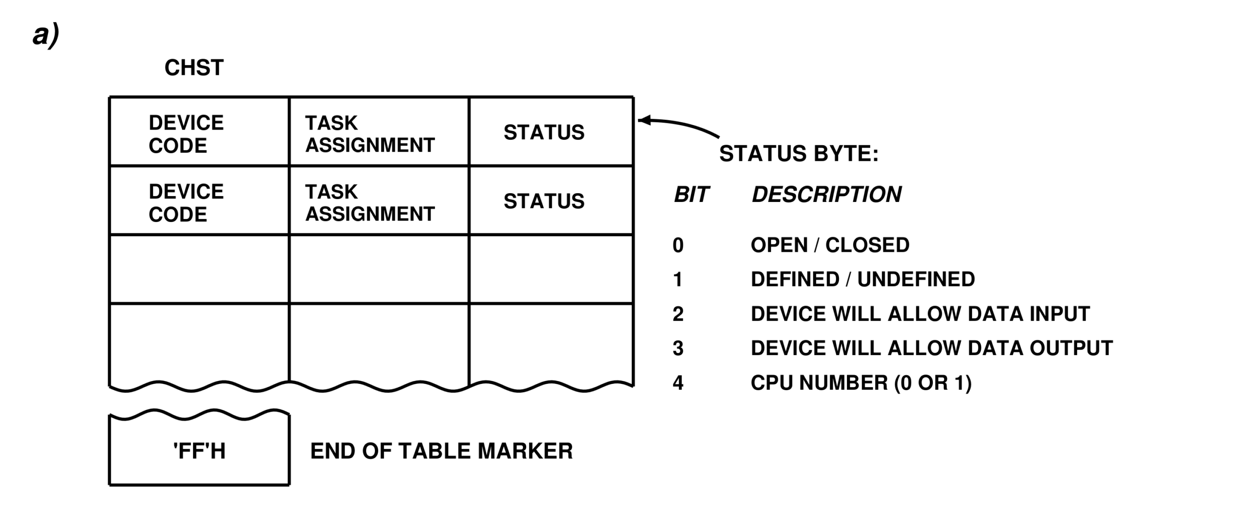
Figure 9a: The channel status table (CHST). Each table entry has a device code, a task assignment byte (hexadecimal FF if unassigned), and a status byte. The table is terminated by an FFH in the first byte of the table entry after the last valid entry.
The Task I/O Table
Another useful innovation is the task I/O table or TIOT. (See figure 9b.) Each task or program must have its own TIOT. The task control table (TCT), discussed in the previously referenced multiprogramming article contains an entry for each task, which includes a pointer to the TIOT for that task. The subroutines that manage the port communications must check the TCT to determine which program called it and the location of the task's I/O table. The TIOT has one entry for each device the program wishes to use. The first byte in a TIOT entry is the unit number that the program will use to refer to the device (ie: 0=console, 1 = keyboard, 2 = printer, etc). The second byte contains the actual device code. This allows the user program to reassign a device by changing the TIOT entry. For example, you may wish to have console output routed to the printer or have keyboard input come from a disk file. This also allows alternate consoles to be defined.
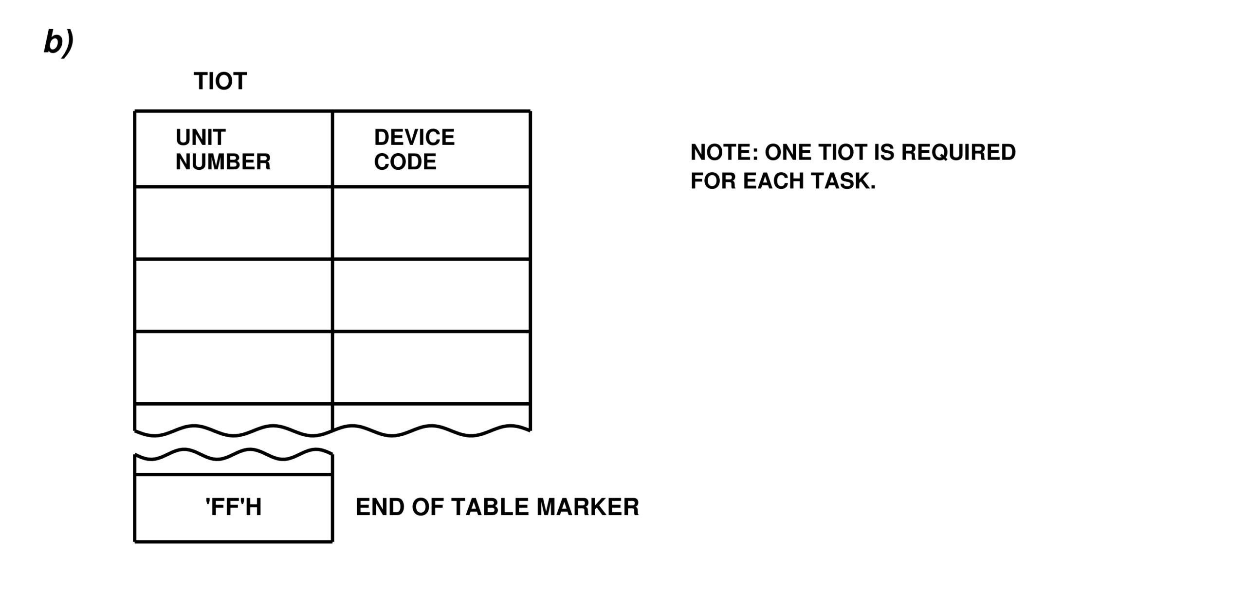
Figure 9b: Shows the task I/O table (TIOT). One TIOT must exist for each task in either processor. A TIOT entry consists of a unit number followed by the assigned device address. Using this scheme, device reassignments are easy to handle.
Shareable Devices
Some devices must be restricted so that no other task can send or receive data from them. The channel-status table (CHST) has a byte reserved for task assignment. When a channel (ie: device code) is opened by a task, the CHST must be updated to keep track of which task opened it. Later, when the task tries to read or write to a device, the CHST is checked to make sure it is legal. Without this checking process, unusual events may occur. For example, suppose two tasks tried to use the same printer? The printout would be a mixture of characters from each task. When the channel is closed, the task assignment byte of the CHST entry is set to hexadecimal FF to indicate that the device address is unassigned.
Opening and Closing Devices
Before any data can be transferred on a channel, it must be opened. This procedure is similar to opening a tape or disk file. The reason for doing this is to explicitly indicate that you wish to start reading or writing. The procedure also has a use when accessing tape or disk. When a device is opened that is assigned to a mass storage file device, the file name may be given instead of a device code. The supervisor should recognize this and establish a device-code link to the tape or disk I/O routine.
Slave-to-Master Interface
We now have a straightforward mechanism for handling the time-multiplexed port going from the master processor to the slave. Since there must also be slave-to-master communications, we could run multitasking on both processors. But in my system I only want to run one program on the master—either the operating system, the assembler, the editor, or an application program. The problem here is similar to the one discussed earlier: without multiple threads of program logic, how can one handle a multiplexed bus? One approach would be to have one master channel (ie: port) I/O subroutine that is called for all input or output requests. The registers would have to be set up before calling the channel to indicate what function (eg: read, write, open, close) is to be performed. Another register would indicate the unit number to operate on, which is found in the task I/O table. Once the subroutine has been called, it will have to perform many things: If the operation to be performed is an output-to-port:
- Check for an acknowledge.
- Check for errors.
- Output the device code.
- Output the data byte. (This should automatically set the data-ready line.)
- Wait for an acknowledge.
- Check for errors on the port.
- If an error has occurred less than five times go to (1) to retry; otherwise, issue a write error.
- Return to calling program.
If the operation is an input, the problem becomes more complex:
- Check for data ready.
- Read in the device code.
- Read in the data and check for parity errors.
- If an error has occurred less than five times issue a parity error, and go to (1) to retry; otherwise, issue a hard I/O error.
- Return to calling program.
At this point there may be difficulties. Suppose the device code of the byte is not the one desired? One alternative is to set up a memory buffer as temporary storage for the bytes that come in but are not needed yet. The other is to force the slave to send only what is wanted and let it do the buffering. In the second case, an input operation, a device address would be reserved for processor-to-processor commands. Whenever the master wants something from the slave, it must issue a request for it on device 0. This makes the slave do the work, and drastically reduces the overhead of the master processor.
Distributing the Workload
As the word is defined, slaves are supposed to do the menial tasks. What else can we make it do? Parallel processing is a possibility. Perhaps it could be made to calculate equations that the master needs at a later time. This type of processing requires tricky programming, but can be done.
Loading and Starting a New Task
Assuming that there is a program to be run on the slave, there must be a manner in which to enter it into the slave and start it. First, either the slave must have sufficient unused memory (at a known address) in which to put the program, or the program must be in a relocatable format that can be loaded at any address and run correctly. Several assemblers and compilers are able to produce relocatable object code that can be translated into absolute addresses and loaded with a small loader program. Second, the master must have some way of adding the new task to the slave's task control table (TCT) to initiate execution. The techniques involved are quite system dependent and will not be discussed here. Once the task is running, it may receive input from the master through an assigned input-device address defined in its task I/O table. Note that most of this discussion on distributing the work load also applies to a tightly-coupled multiprocessor.
Locating Devices on a Multiprocessor
Since both processors may have I/O devices, it is necessary to tell each one what it has and what the other processor has. An extra bit in the status byte of each channel-status table entry could be added to indicate what devices are where. For example, the slave may need to read bytes or blocks from the disk, which is located on the master-processor bus. Also, it is quite possible that a task may wish to communicate directly with another task on the same processor. The solution is to set up a small buffer that will be referred to as an intertask data buffer (ITDB). This buffer contains two bytes, a device code and a data byte. If the device code is set to hexadecimal FF, then the buffer is seen as being empty. When a valid device code is placed in the intertask data buffer and a data byte is loaded into the second location, the transfer request is said to be posted. The standard channel I/O subroutine may be called to perform the post, because it will see that the desired device code is on the same machine. As with any other I/O operation, the post will be performed and the supervisor will again make a coroutine call to switch to another task. An I/O request is always seen as a top priority task, so the supervisor will look in the channel-status table (CHST) to find out which task must be activated, and will transfer control to it. When the task gains control it will be able to call the channel I/O service routine and ask for the incoming byte. The service routine will again recognize that the byte came from an internal task, not the port, and will look in the inter-task data buffer (ITDB). The channel I/O service subroutine must of course have the necessary sequence of instructions to handle this extra buffer. Figure 10 shows the entire set of control blocks and service routines discussed in this section. Figure 11 shows an example, where user task 1 wants to output a byte to unit number 3.
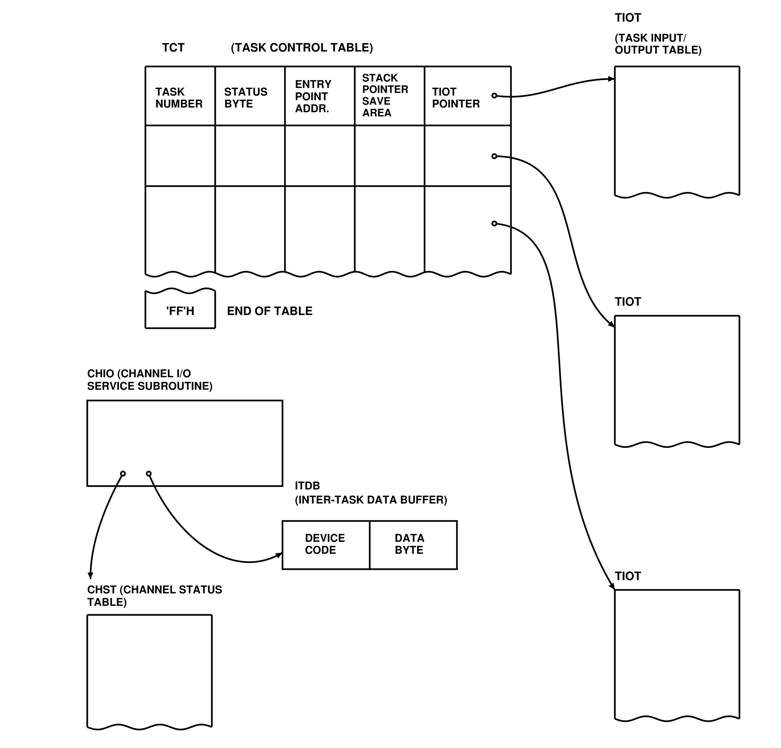
Figure 10: Control tables and blocks. The TCT (task control table) contains entries for each task in a given machine. Each task has (among other things) a pointer to its TIOT. The CHIO (channel input/output) subroutine may be called by any program to receive input or generate output. The CHIO routine has a channel status table which keeps track of each channel (device address) and its status. The ITDB (inter-task data buffer) is an internal buffer used for intertask transfers of data.
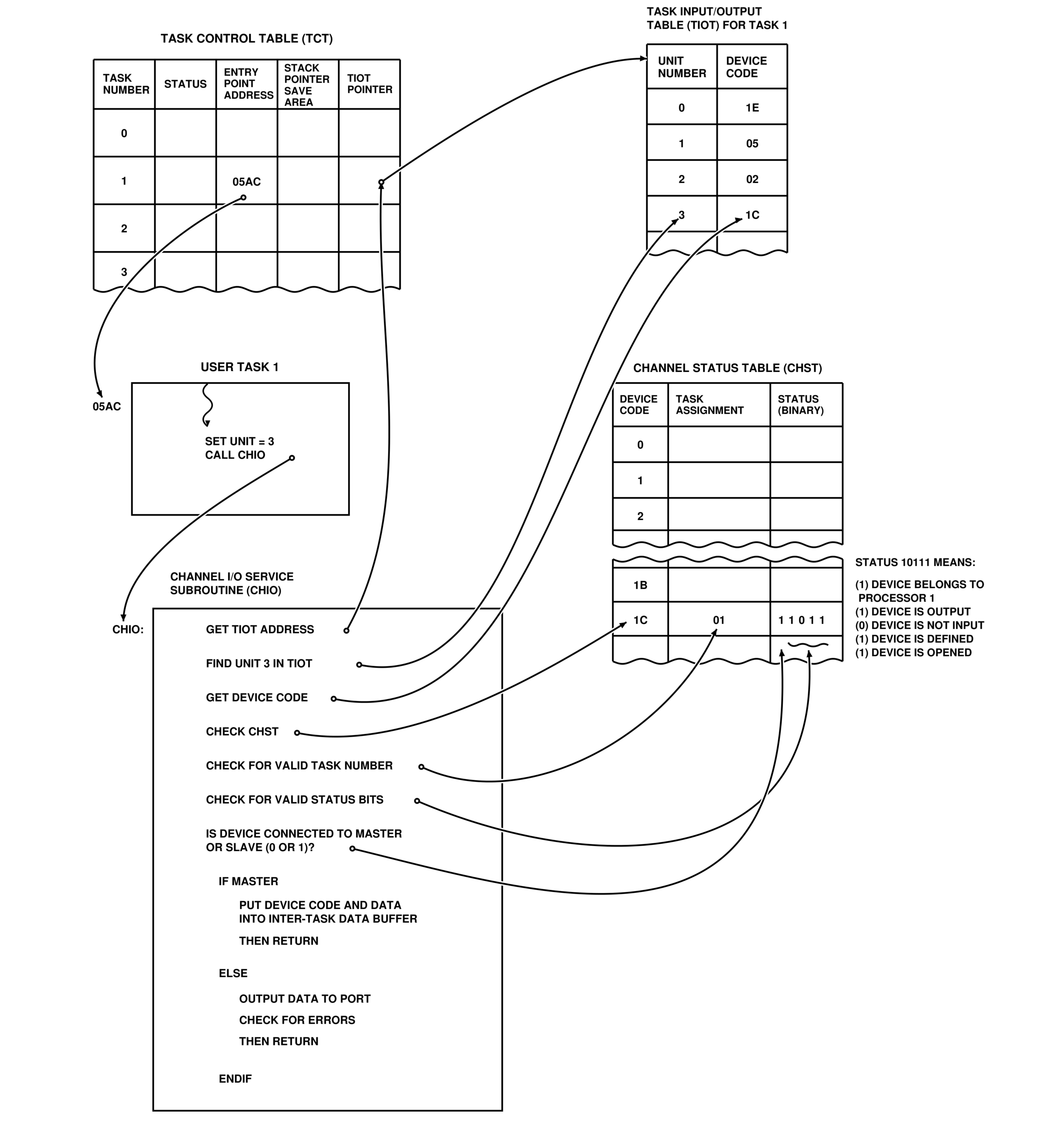
Figure 11: Shown here are the same tables described in figure 10, with the addition of user task 1. This task has loaded the registers and called the channel I/O routine, which will see that task 1 wishes to output a byte to unit 3. First the routine gets the address of task 1's task I/O table by looking in task control table (the task status byte will tell the channel I/O routines which task is active —in this case, task 1). Next, the routine scans the task I/O table to find the unit-device address assignment for unit 3. In this example, the device address for unit 3 is found to be hexadecimal 1C. The routine then scans the channel status table for device 1C. When found, the task assignment byte is checked and verified against the number found previously in the task control table. If they aren't the same, an invalid device code message is generated, and control is returned to the calling task. If they are the same, the channel I/O routine verifies that the device is defined and opened. Lastly, the routine must check the processor number bit to see which processor the device is on, if the device is on the other processor, the data and device code are sent to the port. If the data is to go to a device on this processor the data and device code are put in the inter-task data buffer for the destination task to read.
Summary
It becomes apparent that even a simple master-slave interface may become quite complex if designed with flexibility in mind. Multiprocessing with shared memory blocks may be somewhat easier because the separation between the processors is greater. Each byte of the shared memory could be considered a separate device address, greatly simplifying the amount of buffering and checking that is needed in a tightly-coupled multiprocessor. For the average hobbyist, multiprocessing has always been a curiosity, something that everyone dreams about but few people ever do. This discussion should be treated as a conceptual overview, not as the final word on the subject. I chose the approach described above because of my nonstandard hardware, and also because of my background knowledge and hardware experience. Others may choose totally different and possibly better configurations.
References
- Abrams, Marshal D. and Philip G. Stein. Computer Hardware and Software. Addison-Wesley Publishing Company, Reading MA, 1973.
- Dahmke, Mark C. “Introduction to Multiprogramming” September 1979 BYTE. BYTE Publications, Inc, Peterborough NH.
- Davis, William S. Operating Systems. Addison-Wesley Publishing Company, Reading MA, 1977.
- Hsiao, David K. Systems Programming. Addison-Wesley Publishing Company, Reading MA, 1977.
- Martin, Donald P, Microcomputer Design. Martin Research Ltd. Northbrook IL, 1976.
- Tanenbaum, Andrew S. Structured Computer Organization. Prentice-Hall, Inc. Englewood Cliffs NJ, 1976.