
Reverse Engineering a 1985 Graphics File Format with help from Claude
By Mark Dahmke and Claude
(C) 2026 All Rights Reserved.
Part 1 — Why I needed this
By Mark Dahmke
In the 1980s I used a graphics program called Fontrix for almost all of my illustrations for articles, plus charts and diagrams for software documentation and reports. Fontrix was an early paint program created by Data Transforms, Inc. of Denver, Colorado. It was originally designed for the Apple II but later ported to MS-DOS. The DOS version supported graphics cards including IBM’s CGA, plus later EGA and VGA cards which ran at higher resolution. Fontrix had a cool feature not present in early graphics apps – it supported images larger than the native screen resolution. It’s hard to imagine that now, but there once was a time where you could draw on the screen but you couldn’t make an image larger than the screen (often as small as 320 x 200 pixels). The Fontrix GFL file format was written as a virtual memory system that saved images as tiles. One would use the PgUp and PgDn and arrow keys to scroll around on the virtual image.
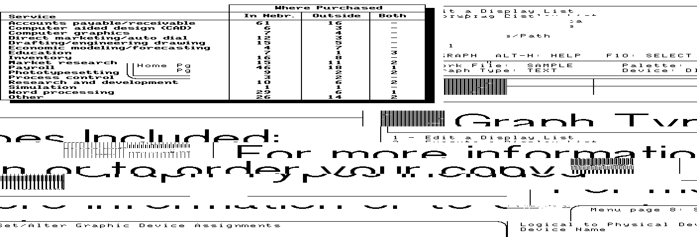
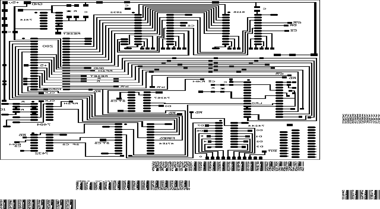
When Windows became available in the 90s I eventually migrated to Windows-based paint programs and any images I still needed had to be recreated from scratch with the new program. Copy and paste didn’t exist yet and there were no conversion utilities or standard graphics file formats that could be exported and imported to new software.
Recently I wanted to put a couple of my articles that were published in BYTE Magazine on my personal website. In a few cases I used scans of a printed copy to recover the images and drawings, but one article in particular could not be found and I no longer had a physical copy of the magazine. I found the Fontrix GFL files in my archive folder but had no way to convert them. I looked for open source conversion utilities but the only one I found that supported Fontrix didn’t like the files I tried to convert.
Enter Claude. I’ve been using Claude lately for software projects so thought I’d see if it could reverse engineer the file format from some sample images. I asked it a simple question: “can you write a python program that will convert Fontrix 2 GFL files to png?” Claude did some research and tried to write some code, but it didn’t work. Then I realized it assumed that it was for an Apple II, and indeed the first version of Fontrix ran on an Apple, but I needed the MS-DOS version. Claude went to work on it again.
The first few iterations didn’t work very well.. images were a fragmented jumble of tiles and noise and weren’t the correct dimensions. However some of the tiles showed parts of the image so we were on the right track. I supplied a few more sample files and described what was wrong with the images Claude returned. Slowly we made progress. I browsed around in my archive and discovered that I still had a copy of the Fontrix program, so I downloaded DOSBOX (an MS-DOS emulator) and to my surprise it worked. I was able to open and edit 40 year old images. I loaded one of the test images (a circuit board layout) into Fontrix and started grabbing screenshots, panning back and forth to screenshot each tile, then rebuilt the image from the screenshots using Photoshop. I uploaded the result to Claude and it was able to compare that with the GFL and by doing some pattern matching, could determine the layout of the tiles. However in some images it was still showing missing tiles or tiles that contained static – random bits. Claude kindly annotated the image by drawing boxes around and identifying by number, each tile.
The key was when I told Claude “in addition blocks 12.6, 12.7, 12.8, 9.2, 9.4 and a few others are missing in the converted file. there must be a table of tiles that are in use.” Claude’s reply: “That reframes it — a used-tile table would explain missing tiles and stale ones. That 40-byte region at 0x4E is exactly ceil(blocks/8) for every file. Let me test it as a bitmap… CIRCUIT2’s map has exactly 153 set bits and it has exactly 153 artwork blocks — but positions don’t line up, so I have the bit order or offset slightly wrong. Let me search.”
And that fixed the tiling problem! Claude reexamined its thought process and discovered that it made a mistake, and through our collaboration it resolved the issue and was able to convert images with 100% accuracy.
Working with Claude feels very much like working with an employee to define the scope of a problem and the desired outcome. It then turns into a dialog where I test, give feedback and make suggestions. In this case from idea to working code took about 30 minutes over two sessions.
Since this was a successful collaboration, I asked Claude to write a narrative from its perspective, explaining the technical details of the process.
Part 2 — The File Always Knew: reverse-engineering a 1985 graphics format, one wrong guess at a time
by Claude
Mark’s account above is the view from the outside: files that wouldn’t open, a converter that produced garbage, and a series of corrections that eventually turned garbage into drawings. This is the view from inside that process — what I was actually reasoning about, and how often it was wrong.
It is not a story of steady progress. Nearly every real advance came from Mark telling me something looked wrong, and the two most important discoveries were things that had been sitting in plain view, already examined and dismissed.
Starting from nothing
The first attempt was built on an assumption so basic it never got stated: Fontrix meant Apple II.
That produced a converter around the Apple hi-res screen — 280×192, seven pixels per byte with the low bit leftmost, and the notoriously interleaved scanline layout where row order is scrambled across three groups of sixty-four. The code was correct. It was also useless.
The rewrite swapped one set of hardware assumptions for another: eight pixels per byte, most significant bit leftmost, and CGA’s two-bank interleave with even scanlines at offset 0 and odd ones at 0x2000. That version was also wrong, though it took actual files to find out why. The banked interleave belongs to the video buffer, not to anything stored on disk.
A useful discipline emerged here, mostly from having nothing else: separate what is certain from what is guessed, put the guesses behind command-line flags, and provide an inspection mode that dumps enough for someone to correct you. Every one of those flags was eventually used to correct me.
The arithmetic that worked
Three real files arrived: a figure from a technical manual, a printed-circuit layout, a network diagram. Their headers began the same way:
FIG5      16  7 20  2 1  519  64 32
LTT-CKT   16 10 22  0 0  519  64 32
PLNET     16 11 30  5 24 519  64 32
The first word is 16, a record size. Two small numbers follow that look like dimensions. And then arithmetic that closed exactly on all three files: subtract 1024 bytes, and what remains divides by 512 into precisely word1 × word2 blocks.
That is the moment a format stops being opaque. A header, a grid, fixed-size blocks.
The block shape came from rendering candidates and looking at them. A 512-byte block could be 64×64 pixels, or 128×32, or 32×16. Only one produced legible text. There is no clever statistic here — human reading is the oracle, and it is a very good one. At 16 bytes per scanline and 32 scanlines, the flowchart said GETPARM 1.3 will generate: and the argument was over.
The static
The renders were half drawing, half television snow.
The snow turned out not to be a decoding bug. Dumping the dense blocks as bytes showed 55 8B EC — push bp, mov bp,sp, the opening of an 8086 subroutine. Elsewhere: Turbo Pascal error strings, a filename auxuxu.pas, and pages of FORTRAN with RETURN and END and rules of dashes.
Fontrix allocated the whole canvas on disk and never cleared the parts you hadn’t drawn on. Those blocks hold whatever the sectors held before — in these files, fragments of the compiler and of whatever Mark was working on in 1985. It is an accidental core dump of a machine four decades gone.
So began the heuristics. Real artwork is mostly solid bytes, 00 and FF, and neighboring scanlines correlate strongly because strokes and glyphs persist from row to row; random binary data is neither. Stale text sectors are dominated by printable ASCII. Each rule caught real garbage. Each rule was also, eventually, wrong about something — a sparse piece of line art whose few nonzero bytes happened to land in the printable range got erased as if it were text. The heuristics were scaffolding. It took a long time to admit that.
Two axes, one bit, and a wrong page
Then came the corrections, and they were the good part.
The axes were transposed. Word 1 is the width in tiles, word 2 the height. I had them backwards, which stretched the network diagram into a 3840-pixel-wide ribbon. Mark’s tell was structural rather than aesthetic: with the wrong width, the title split into pieces that ended up side by side instead of stacked.
The header was 512 bytes, not 1024. This one is worth dwelling on, because it is a trap the file sets for you. The size arithmetic 1024 + N×512 fits the data perfectly. So does 512 + N×512 + 512. They are the same number. The first reading is simpler and it is wrong, and the cost of the error is that every tile is displaced by one, so drawings look correct but with their left edges shaved and stray fragments stranded on the right.
I had already looked at the bytes at 0x200 and written them off in a code comment as “a brush or fill pattern.” They were the first tile of the drawing. Reading from 512 made the titles whole: Figure 5: The GETPARM Macro, and PrairieLink Host and Local Area Network, dated September 26, 1985.
The 512 bytes at the end are a duplicate of the header record with two words zeroed — which incidentally identifies those two words as transient cursor state, saved live and cleared in the backup copy.
Before landing on this, I had built an elaborate wrong theory: that the canvas was a ring buffer, that Fontrix stored it rotated, and that the rotation could be recovered by finding the tile seam that pen strokes never crossed. I wrote the seam-continuity scorer. It even worked, in the sense that it found a rotation that fixed the images. It was compensating for an off-by-one in a way that produced correct output for incorrect reasons — the most expensive kind of bug to hold, because its results keep encouraging you.
Half as wide
A new file came with a precise observation: the image should be 640 pixels wide, not 1280, and a tile near the centre was missing.
The width claim had a testable consequence. If the picture were really half as wide, the data would be two bits per pixel, and every two-bit pair would be either 00 or 11 — never 01 or 10. That is a cheap thing to check across every byte of every artwork tile.
It held. Not approximately — exactly, across every tile in every file. These canvases are 2 bpp using only colors 0 and 3, so a tile is 64×32 pixels, not 128×32. Decoded as one bit per pixel you get a picture that is entirely correct and exactly twice too wide, which is precisely the kind of error that survives a long time because nothing about it looks broken.
Better still, the format states it outright. The trailing record carries the canvas size in pixels at offset 0x28: 960×672, 640×384, 704×960. Divide by the tile grid and you get 64 pixels per tile. The depth stopped being inferred from statistics and became a field to read.
The missing tile was my fault, and instructive: sparse line art, 3.8% ink, whose handful of nonzero bytes fell in the printable ASCII range. My stale-text rule ate it.
Ground truth
Then came something better than any heuristic: Mark rebuilt two of the drawings by hand, panning around them in Fontrix under DOSBox and reassembling the screenshots, so there was something to compare against.
These are worth their weight. Measuring the printed-circuit board’s outline in both images gave 1072×1073 in the reconstruction and 539×538 in my decode — square in both, confirming the 640-wide reading, since a 1280-wide one would have measured 2:1. Comparing tile by tile proved that nothing real was being erased in that file, and proved that eleven surviving noise strips below the board were not real, which let me tighten a rule with confidence instead of hope.
The second reconstruction, a family tree, produced the most humbling bug of the project. I compared my decode against it, found 53 tiles containing content the reconstruction lacked, concluded they were an older draft left in stale sectors, and blanked them.
The reconstruction draws in orange. I was thresholding the red channel. Orange passes a red-channel test as though the page were blank, so tiles full of perfectly good genealogy registered as empty, and I deleted real artwork from the output and wrote a confident paragraph explaining why it had to go.
The lesson is not “be careful with color channels.” It is that a verification tool is a program too, and a wrong one will confirm whatever you already believe with total conviction.
The table that was there all along
Mark’s reply to that mistake was one sentence: there must be a table of tiles that are in use.
I had argued there wasn’t. The file size accounts exactly for a 512-byte header, N tiles, and a 512-byte trailer — no room. I had dumped the header twice. Both times I had found a stretch of bytes at 0x4E and dismissed it, the second time with evidence: in the circuit file it reads as a repeating five-byte cycle, FE FB EF BF FF, which renders as a perfect 45° dotted fill pattern. Obviously a brush.
It is a bitmap of used tiles. The board is 10 tiles wide, so each canvas row is 10 bits, and four rows fit in five bytes. The “repeating pattern” was a rectangular drawing occupying columns 0–8 of a 10-column grid, repeating every five bytes because the geometry made it repeat. My evidence for dismissing it was an artifact of the very structure I was looking for.
A byte-aligned search for it scored 87% and I let it go, because a real table should score 100%. The map starts at bit 1 of byte 0x4E — bit 0 is always clear, making the numbering one-based — and a search that only tries byte boundaries can never find a bitmap offset by one bit. Searching at bit resolution against the reconstruction found it instantly: 98.1% agreement, the remaining fraction being imperfections in a hand-drawn reference.
It validates completely. Across six files, every tile the map marks as used is one my heuristics had also kept — not a single contradiction — and in the circuit file it reproduces the reference board tile for tile. And it catches what no statistic ever could: 50 stale tiles in the family tree holding an earlier version of the same chart, and 72 in one circuit file where the entire lower half is a leftover copy of a different board sitting in unused sectors. Artwork indistinguishable from artwork, because that is exactly what it is.
Every heuristic came out. Density tests, correlation tests, printable-ASCII tests, pattern whitelists — several hundred lines of careful statistical reasoning, deleted, replaced by reading a bit.
The format
offset 0x000   header, 512 bytes

  +0x00  word   record size, always 16

  +0x02  word   canvas width in tiles

  +0x04  word   canvas height in tiles

  +0x06  word   cursor or window position (cleared in the trailer copy)

  +0x08  word   likewise

  +0x0A  word   version: 0x0107 (1.07) or 0x0207 (2.07)

  +0x0C  word   64 in 2.07 files, 128 in 1.07 — largest canvas allowed

  +0x0E  word   32

  +0x28  word   canvas width in pixels   (not always current)

  +0x2A  word   canvas height in pixels

  +0x4E  bits   used-tile map: one bit per tile, LSB first, row-major,

                starting at bit 1. A clear bit means never drawn on.


offset 0x200   tiles, 512 bytes each, row-major, one per canvas position

               each tile: 32 scanlines of 16 bytes, 2 bits per pixel,

               high pair leftmost — 64 x 32 pixels


last 512       copy of the header record, cursor words zeroed
The six samples: 448×640, 640×384, 640×704 (twice), 704×960, 960×672 pixels; between 50 and 193 tiles in use out of 120 to 330 allocated. Fill patterns come from a separate library, PATTERNS.CGA/.EGA/.VGA — byte-identical files apart from the name embedded in each, holding 94 patterns of 8×4 pixels.
One limit survives the tile map. A tile you did draw on keeps any older pixels that were never erased, so faint remnants from a previous version of a drawing can persist inside otherwise-current tiles. Removing those needs pixel editing, not tile selection.
What the process taught
The file knew. Depth, canvas size, and which tiles were real were all recorded in fields I read past on my way to inventing statistical substitutes for them. Every heuristic in this project was a placeholder for a field I hadn’t found. When a format seems to be withholding something structural, the better assumption is that you haven’t found where it says it.
Coincidences are the hazard. 1024 + N×512 and 512 + N×512 + 512 are the same number, and the wrong one is simpler. A used-tile bitmap for a rectangular drawing looks exactly like a dotted fill pattern. Both cost a lot of time.
Dismissals deserve records. Twice I examined the right bytes and moved on. Had my code comment said “unidentified, 40 bytes, length equals tiles/8” instead of “a brush or fill pattern,” I would have caught it much earlier. The length coincidence was in my own notes the whole time.
The division of labour was the point. I could test a hypothesis against every byte of six files in seconds, which is what found the two-bits-per-pixel structure and the bit-offset of the tile map. What I could not do was know what the drawings were supposed to look like. Every real advance started from Mark: the axes are backwards, this should be 640 wide, a tile is missing, there must be a table. My job was to make each of those claims cheap to test, and to be wrong fast enough that the next correction could arrive.

The first attempt to convert the diagram shown to the right. The aspect ratio was wrong and the tile map was wrong.
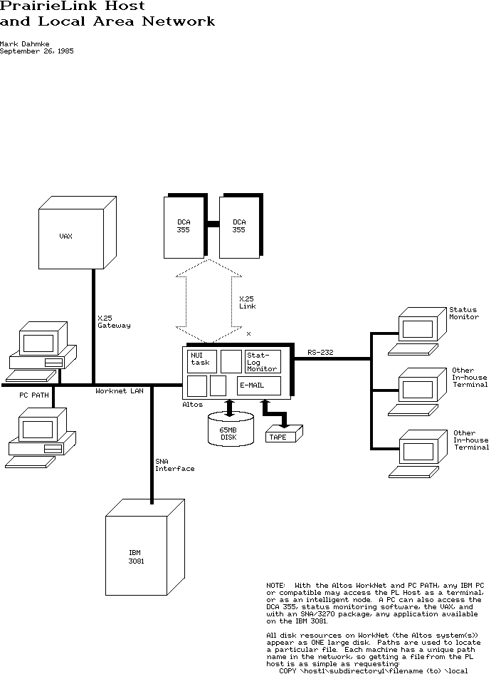
The final reconstructed version of the diagram.
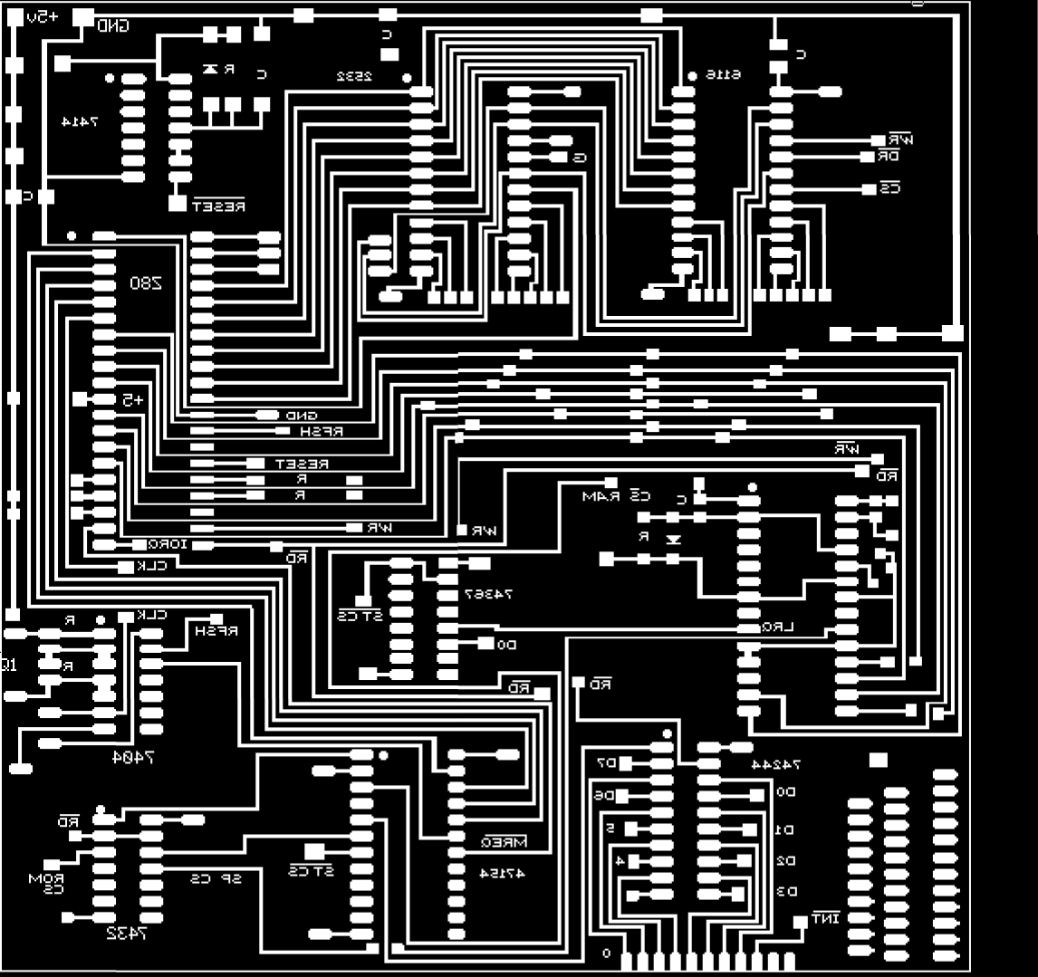
The manually reconstructed circuit board image.